
Crown Victoria V8-281 4.6L SFI (1998)
5.
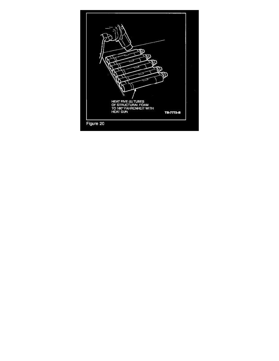
Put the five (5) tubes of 1U2J-19554-DA Motorcraft Structural Foam on a table and heat the tubes front and back with a heat gun to approximately
71.1 °C (160 °F). This will help soften the two parts of the Structural Foam so that it will flow out of the tubes and through the mixing wand easily
(Figure 20).
6.
Remove the small black plugs from a tube of structural foam. Install the nozzle (4W73-19H255-M) and replace the holding nuts. Balance the
plungers by gunning out some material. Ensure that it comes out from both tubes. Press the tab on the back of the gun to relieve pressure. This will
prevent the foam from streaming out of the tube uncontrollably.
7.
Insert the nozzle through the hole cut into the duct tape in the outside tooling hole (Figure 19). Pump the tube of Structural Foam into the frame
rail. When the Structural Foam rises to the height of the tooling hole, it will be necessary to duct tape the hole when switching tubes to prevent
leakage of the Structural Foam.
NOTE
REPEAT STEPS 6-7 UNTIL ALL FIVE (5) TUBES OF 1U2J-19554-DA MOTORCRAFT STRUCTURAL FOAM HAVE BEEN PUMPED INTO
THE FRAME. ALLOW AT LEAST THIRTY (30) MINUTES FOR THE STRUCTURAL FOAM TO CURE BEFORE REMOVING THE DUCT
TAPE.
8.
Raise the vehicle all the way up.
9.
Remove duct tape.
10.
Brush on Motorcraft PM-12-A Low Temperature Anti-Corrosion Coating to the weld areas.
REASSEMBLE FRAME AND BODY
In the following steps the frame will be reassembled to the body, and the bumper fascia will be reinstalled.
NOTE
REQUIRED ONLY IF THE "REAR FRAME AND BODY SPLIT" PROCEDURE WAS PERFORMED.
1.
Partially raise the vehicle.
2.
Reinstall a 2X6 block of wood and two (2) jackscrews up tight against the body between the body drain plugs, partially under the trunk and the
fuel tank (Figure 9).
3.
Lower the hoist until the 2X6 block fits snug against the body.
4.
Remove the wood block between the frame and the body mounts at the # 5 body mount location on each side of the vehicle (Figure 10). It may be
necessary to further lower the hoist by 6 to 12 mm (1/4" to 1/2").
5.
SLOWLY raise the hoist until the frame is off the jackscrews and is flush with the body. Watch the bumper cover to make sure that it does not