
Crown Victoria V8-281 4.6L SFI (1998)
Speedometer Head: Service and Repair
Electronic Instrument Cluster
NOTE: The electronics within the instrument cluster are NOT serviceable. For a confirmed electronic failure, return the entire assembly to the
manufacturer (packaged carefully to avoid damage to the vacuum fluorescent displays and other electronic components). Instrument cluster should be
disassembled only to service plastic defects.
Federal law requires that the odometer in any replacement speedometer/odometer must register the same mileage as that registered on the removed
speedometer/odometer. Service replacement speedometer/odometers and odometer modules with the mileage preset to actual vehicle mileage are
available through Ford Electronic Service Centers. In nearly all instances, the mileage continues to accumulate in the odometer memory even if the
odometer does not display mileage. This mileage can usually be verified by the electronic service centers. Contact the service center for instructions to
receive a replacement speedometer! odometer or odometer module with the mileage preset to actual mileage.
If the actual vehicle mileage cannot be verified, the service center will supply a speedometer/odometer or odometer module with the odometer display
preset to zero ("0") miles and the service odometer segment ("s") illuminated in the vicinity of the odometer display. In addition, an odometer mileage
sticker is supplied with the replacement odometer. This sticker must display the estimated vehicle mileage and is to be affixed to the driver door.
REMOVAL
1. Disconnect battery ground cable.
2. Set parking brake.
3. Unsnap LH instrument panel moulding and RH instrument panel moulding and remove from instrument panel finish panel.
4. Remove instrument panel steering column cover.
5. Remove four nuts retaining the steering column and lower the steering column.
6. Remove knob from headlamp switch.
7. Remove 13 screws retaining instrument panel finish panel and pull instrument panel finish panel out.
8. Move gearshift lever to low gear (1) position if required for easier access.
9. Disconnect electrical connecters from message center switch module.
10. Remove instrument panel finish panel carefully so not to scratch the instrument cluster lens.
11. Disconnect electrical connector from front of instrument cluster.
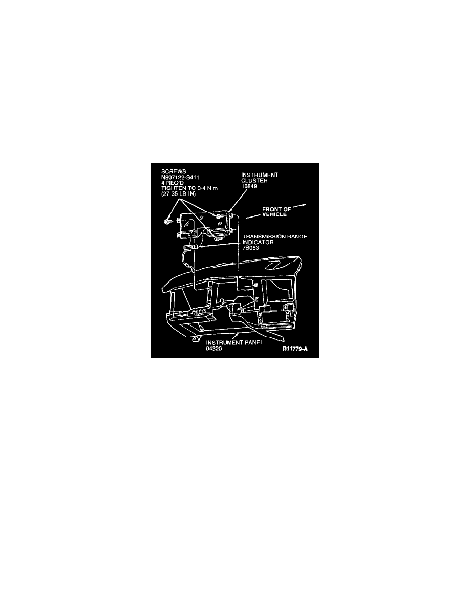
12. Disconnect transmission range indicator from instrument cluster by carefully bending bottom tab down and pulling transmission range indicator
assembly forward.
13. Remove four screws retaining instrument cluster. Pull instrument cluster out and disconnect electrical connectors on rear of instrument cluster.
14. Remove instrument cluster.
INSTALLATION
1. Follow removal procedure in reverse order.
2. Tighten the instrument panel finish panel retaining screws to 3-4 N.m (27-35 Lb-In).