
Crown Victoria V8-281 4.6L SFI (1998)
Spindle: Service and Repair
REMOVAL
1. Raise the front of the vehicle and position safety stands under both sides of the frame just behind the front suspension lower arm.
2. Remove wheel and tire.
3. Remove the front disc brake rotor, disc brake caliper, front disc brake rotor shield and front brake anti-lock sensor if equipped. Discard caliper
mounting bolts. See Brakes and Traction Control.
4. Disconnect the tie rod end from the front wheel spindle using Tie Rod End Remover TOOL-3290-D or equivalent.
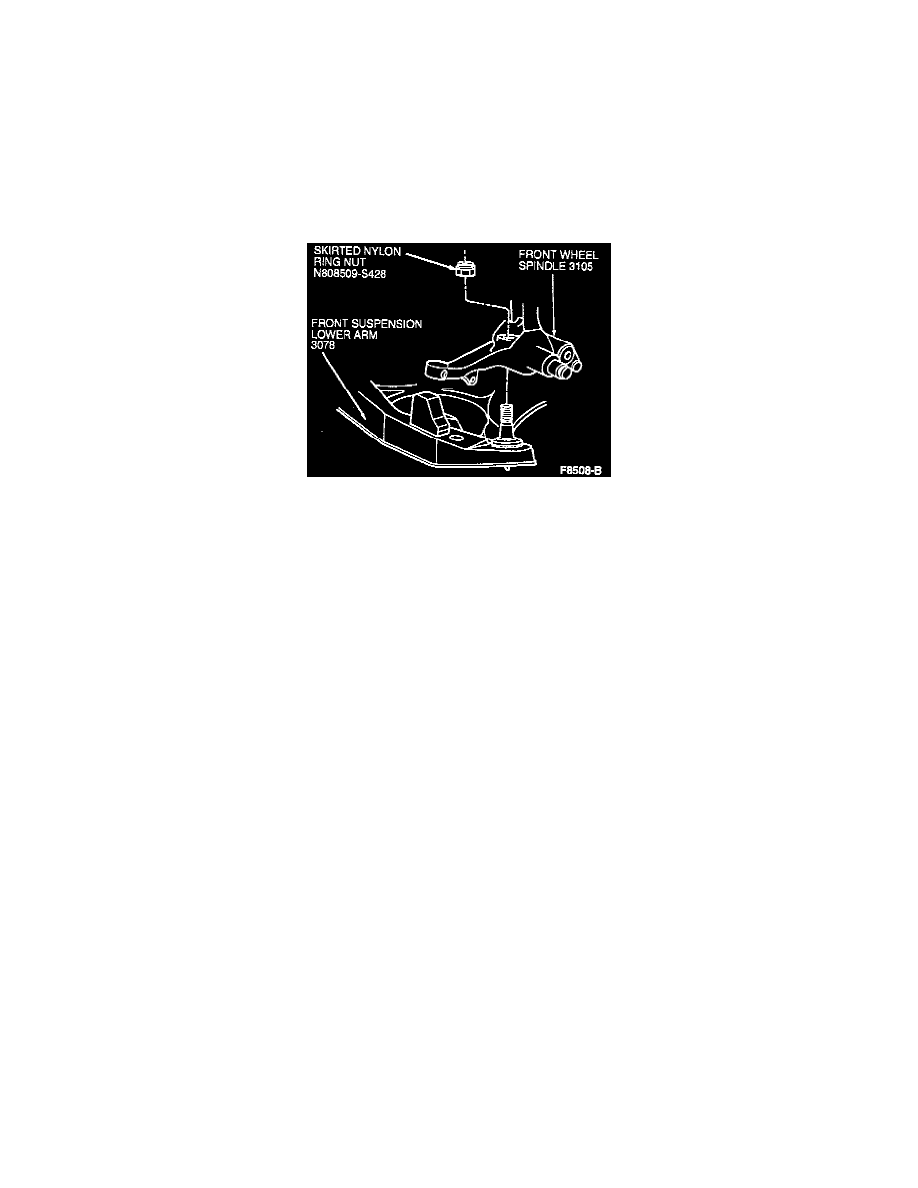
5. Loosen the nylon ring nut from lower ball joint stud and loosen one or two turns. Do not remove the nut at this time.
6. With a hammer, sharply hit the front wheel spindle near the stud to loosen the stud from the front wheel spindle.
7. Loosen front stabilizer bar link nut at front wheel spindle until nut is above thread on ball stud. Using a hammer, strike the nut to displace the
stabilizer bar link from the front wheel spindle. Remove and discard nut.
8. Remove pinch bolt from upper ball joint and stabilizer ball link joint at front wheel spindle.
9. Position a floor jack under the front suspension lower arm at the lower ball joint area and raise jack to support front suspension lower arm.
10. Remove the lower ball joint stud nut. Remove the front wheel spindle. Pry the slot with a suitable pry bar at the upper ball joint to separate from
front wheel spindle.
INSTALLATION
1. Position front wheel spindle on upper ball joint stud. Install pinch bolt and loosely install nut.
2. Position front wheel spindle and front suspension lower arm and insert stabilizer bar link into tapered hole in front wheel spindle. Install nut.
Tighten to 26-35 Nm (20-25 ft. lbs.).
NOTE: Skirt can be removed from nut provided sufficient load of 889 N (200 lbs.) can be generated between ball joint stud and spindle taper.
3. Position the front wheel spindle on the lower ball joint stud and install a new skirted nylon ring nut. Tighten the nut to 148-201 Nm (110-148 ft.
lbs.).
Raise the front suspension lower arm and guide the upper ball joint stud into the front wheel spindle. Install the pinch bolt and nut.
4. Tighten the upper ball joint pinch bolt nut to 76-104 Nm (56-76 ft. lbs.) and remove floor jack.
5. Connect the tie rod end to the front wheel spindle. Install the nut and tighten to 47-63 Nm (35-46 ft. lbs.). Continue to tighten until slot for cotter
pin is aligned. Install a new cotter pin.
6. Install the front disc brake rotor shield, front disc brake rotor, disc brake caliper and front brake anti-lock sensor if equipped. Use new caliper
mounting bolts. See Brakes and Traction Control.
7. Install the wheel and tire assembly.
8. Remove the safety stands and lower the vehicle.
9. Check caster, camber and toe. Adjust as required.