
Crown Victoria V8-281 4.6L SFI (1998)
Differential Case: Service and Repair
Differential Case Disassembly and Assembly
DISASSEMBLY
1. Remove and discard the 10 rear axle differential ring gear bolts securing the ring gear to the differential case.
NOTE: It is not necessary to remove the differential cone and roller assemblies from the case journals unless they are damaged. If the bearings
remain on the differential case during service, keep them clean and free from foreign material.
2. Remove the ring gear by tapping the gear with a soft-faced hammer or press the gear from the differential case.
3. Remove the differential pinion shaft lock pin and remove the differential pinion shaft.
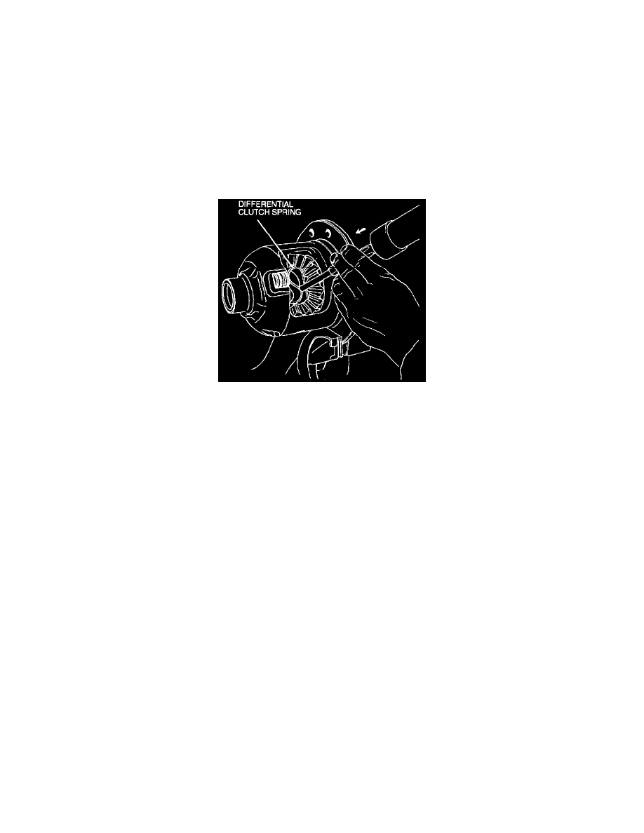
4. With a suitable drift, drive out the S-shaped differential clutch spring.
WARNING: USE CARE WHEN REMOVING THE DIFFERENTIAL CLUTCH SPRING BECAUSE OF SPRING TENSION.
5. Rotate the differential pinion gears until the differential pinion gears and differential pinion thrust washers can be removed.
6. Remove the differential side gears, differential clutch packs and rear axle differential clutch shims from the RH and LH cavities and tag them
"RH" and "LH."
7. Clean and inspect all parts for wear or damage. Replace as necessary.
NOTE: Do not use cleaning solvents on friction plate surfaces. Wipe clean only.
8. Adjust clutch pack preload.
ASSEMBLY
1. Lubricate all parts with specified rear axle lubricant. Soak all clutch plates in Additive Friction Modifier C8AZ-19B546-A or equivalent meeting
Ford specification EST-M2C118-A for fifteen minutes before assembly.
2. Mount the differential case in a soft-jaw vise and place the differential clutch packs and differential side gears in their proper cavities in the
differential case.
3. Engage the differential pinion gears and differential pinion thrust washers with the differential side gears.
4. Rotate the differential pinion gears until the bores in the differential pinion gears are aligned with the differential pinion shaft holes in the
differential case.
5. With a soft-faced hammer, install the S-shaped differential clutch spring in the differential case. If necessary, complete the installation of
differential clutch spring with a brass drift.
NOTE: Inspect the differential clutch spring for damage.