
Crown Victoria V8-4.6L CNG SOHC VIN 9 (1999)
5.
Remove inertia switch cover-to-bracket retaining screws. See Figure 2. Retain screws for installation purposes.
NOTE: The inertia switch and inertia switch cover will be removed as an assembly.
6.
Position inertia switch assembly away from inner quarter panel reinforcement. DO NOT disconnect inertia switch electrical connector.
7.
Remove and discard inertia switch bracket and J-nut. Retain screw for installation purposes.
8.
Measure, mark and drill bottom anti-rotation hole as follows:
^
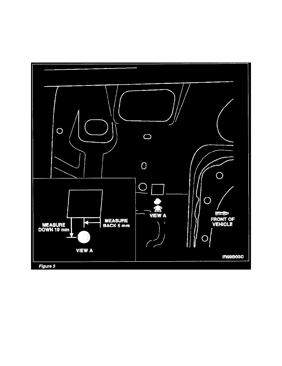
Locate square-cut hole in inner quarter panel reinforcement. See Figure 3.
^
From corner of hole shown in Figure 3, measure directly back 5 mm. Place a temporary mark at this location.
^
From the temporary mark, measure directly down 10 mm. See Figure 3. Center punch this new location.
^
Using a 25/64 inch drill bit, drill hole at center punched location.