
Crown Victoria V8-4.6L Flex Fuel (2008)
Remove the intermediated shaft pinch bolt and detach the intermediate shaft from the steering gear and position aside.
4. Remove the 2 exhaust manifold heat shield bolts and the shield.
5. Remove the catalytic converter-to-exhaust manifold nuts and position aside the catalytic converter flange.
^
Discard the nuts.
6. Disconnect the EGR system module tube from the exhaust manifold.
7. Disconnect and remove the LH heated oxygen sensor (HO2S). For additional information, refer to Computers and Control Systems.
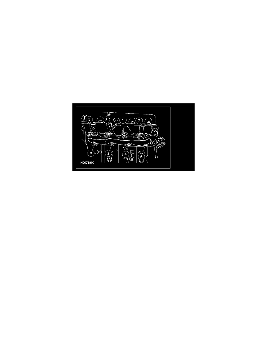
8. Remove the 8 nuts, the exhaust manifold and the gasket.
^
Discard the nuts and gasket.
9. Remove and discard the 8 exhaust manifold studs.
10. Inspect the exhaust manifold for flatness.
Installation
1. Install the 8 new exhaust manifold studs.
^
Tighten to 12 Nm (9 ft. lbs.).
2. Install a new exhaust manifold gasket, the exhaust manifold and 8 new nuts.
^
Tighten in sequence shown to 20 Nm (15 ft. lbs.).
3. Install and connect and the LH HO2S.
^
Tighten to 43 Nm (32 ft. lbs.).
4. Connect the EGR system module tube to the exhaust manifold.
^
Tighten to 40 Nm (30 ft. lbs.).
5. Position the catalytic converter flange and install the new catalytic converter-to-exhaust manifold nuts.
^
Tighten to 48 Nm (35 ft. lbs.).
6. Install the exhaust manifold heat shield and the 2 bolts.
^
Tighten to 10 Nm (89 inch lbs.).
7. Position the intermediate shaft on the steering gear and install the pinch bolt.
^
Tighten to 30 Nm (22 ft. lbs.).
8. WARNING: If the vehicle is equipped with a fire suppression system, repower the system. For important safety warnings and
procedures, refer to Fire Suppression System. Failure to follow these instructions may result in serious personal injury.
If equipped with fire suppression system, repower the system.