
Crown Victoria V8-4.6L VIN W (2000)
Ignition Switch Lock Cylinder: Service and Repair
Ignition Lock Cylinder - Non Functional
Installation
Installation
WARNING: Always wear safety glasses when repairing an air bag Supplemental Restraint System (SRS) vehicle and when handling an air
bag module. This will reduce the risk of injury in the event of an accidental deployment.
WARNING: Carry a live air bag module with the air bag and trim cover pointed away from your body. This will reduce the risk of injury in
the event of an accidental deployment.
WARNING: Do not set a live air bag module down with the trim cover face down. This will reduce the risk of injury in the event of an
accidental deployment.
WARNING: After deployment, the air bag surface can contain deposits of sodium hydroxide, a product of the gas generant combustion that
is irritating to the skin. Wash your hands with soap and water afterwards.
WARNING: Never probe the connectors on the air bag module. Doing so can result in air bag deployment, which can result in personal
injury.
WARNING: Air bag modules with discolored or damaged trim covers must be replaced, not repainted.
WARNING: Vehicle sensor orientation is critical for proper system operation. If a vehicle equipped with an air bag Supplemental Restraint
System (SRS) is involved in a collision, inspect the sensor mounting bracket and wiring pigtail for deformation. Replace and properly
position the sensor or any other damaged Supplemental Restraint System (SRS) components whether or not the air bag is deployed.
WARNING: To avoid accidental deployment and possible personal injury, the backup power supply must be depleted before repairing or
replacing any front or side air bag Supplemental Restraint System (SRS) components and before servicing, replacing, adjusting or striking
components near the front or side air bag sensors, such as doors, instrument panel, console, door latches, strikers, seats and hood latches.
The side air bag sensors are located at or near the base of the B-pillar.
To deplete the backup power supply energy, disconnect the battery ground cable and wait at least one minute. Be sure to disconnect auxiliary
batteries and power supplies (if equipped).
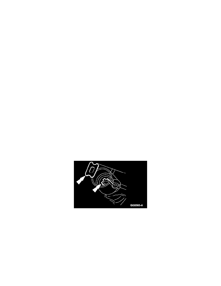
Note: The narrow section of the keyhole in the lock gear must be in the one o'clock position.
1. Install the steering column lock gear and bearing.
^
Use Ignition Lock Grease F0AZ-19584-A or equivalent meeting Ford specification ESA-M1C232-A to coat the steering column lock gear and
the steering column lock housing bearing.
^
The narrow section of the keyhole must be in the one o'clock, with the tab inboard at the three o'clock position. Rotate it counterclockwise.