
Crown Victoria V8-4.6L VIN W (2000)
Heated Glass Control Module: Diagnostic Aids
HOW TO FIND ELECTRICAL CONCERNS
TROUBLESHOOTING STEPS
These six steps present an orderly method of troubleshooting.
Step 1. Verify the concern.
^
Operate the complete system to check the accuracy and completeness of the customer's complaint.
Step 2. Narrow the concern.
^
Using the wiring diagrams, narrow down the possible causes and locations of the concern to pinpoint the exact cause.
^
Read the description notes at the components and study the wiring schematic. You should then know enough about the circuit operation to
determine where to check for the trouble.
Step 3. Test the suspected cause.
^
Use electrical test procedures to find the specific cause of the symptoms.
^
The component location reference bars and the pictures will help you find components. Component location information for connectors,
diodes, resistors, splices and grounds can be found at Vehicle Locations.
Step 4. Verify the cause.
^
Confirm that you have found the correct cause by connecting jumper wires and/or temporarily installing a known good component and
operating the circuit.
Step 5. Make the repair.
^
Repair or replace the inoperative component.
Step 6. Verify the repair.
^
Operate the system as in Step 1 and check that your repair has removed all symptoms without creating any new symptoms.
Some engine circuits may need special test equipment and special procedures. See Testing and Inspection for the specific component, system, or
sub-system in question.
NOTE: Most Ford testing and inspection procedures will be found at the system/sub-system level; only a few component tests are provided by
OE.
TROUBLESHOOTING TOOLS
JUMPER WIRE
This is a test lead used to connect two points of a circuit. A Jumper Wire can bypass an open to complete a circuit.
WARNING: Never use a jumper wire across loads (motors,etc.) connected between hot and ground. This direct battery short may cause
injury or fire.
VOLTMETER
A DC Voltmeter measures circuit voltage. Connect negative (- or black) lead to ground, and positive (+ or red) lead to voltage measuring point.
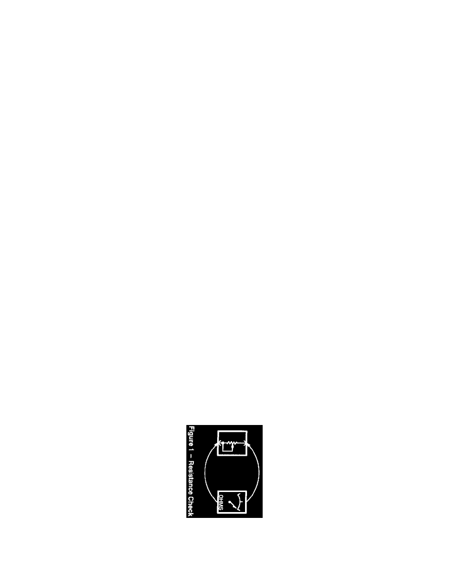
OHMMETER
An Ohmmeter shows the resistance between two connected points.
TEST LAMP