
E 150 V8-4.6L SOHC VIN W (2004)
which is the input to the torque based strategy.
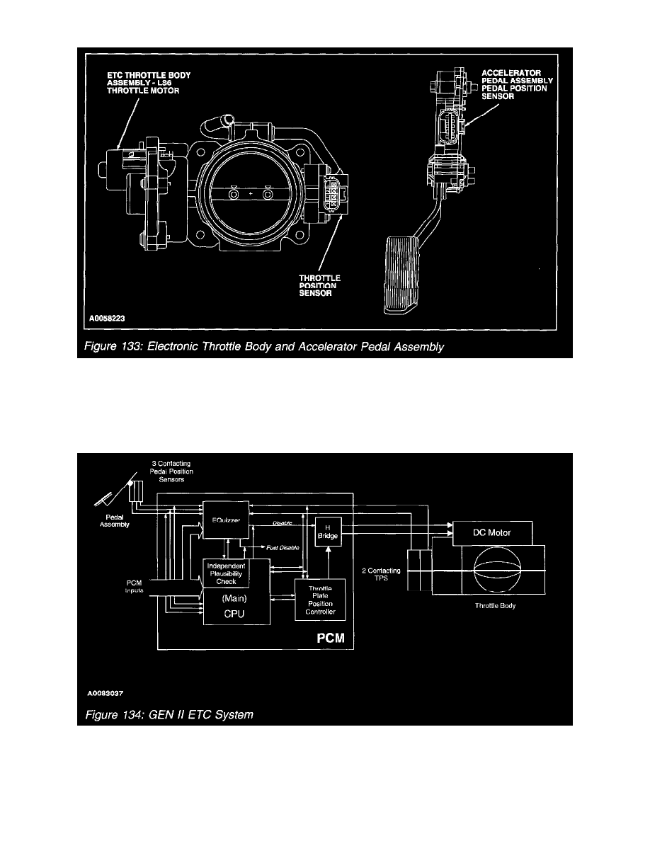
Electronic Throttle Body And Accelerator Pedal Assembly
4. The three pedal position signals ensure a correct input to the PCM, if any one signal has a fault. The PCM knows if a signal is wrong by
calculating where it should be, inferred by the other signals. A value will be substituted for a faulty signal if two out of the three signals are bad.
Electronic Throttle Control System Strategy
GEN II ETC System
As stated earlier the torque based ETC strategy was developed mainly to improve fuel economy and to accommodate Variable Cam Timing. This is
possible by not coupling the throttle angle to the drivers pedal position. By uncoupling the throttle angle (produce engine torque) from pedal position
(driver demand). This allows the powertrain control strategy to optimize fuel control and transmission shift schedules while delivering the requested
wheel torque. ETC is used on the 2004 MY Lincoln LS and Ford Thunderbird, Explorer/Mountaineer, and the new light-duty F-series.