
E 150 V8-4.6L SOHC VIN W (2004)
Variable Valve Timing Actuator: Description and Operation
VARIABLE CAM TIMING SYSTEM
Overview
Variable Cam Timing (VCT) enables rotation of the camshaft(s) relative to the crankshaft (phase-shafting) as a function of engine operating
conditions. There are four types of VCT systems.
-
Exhaust Phase Shifting (EPS) system - the exhaust cam is the active cam being retarded.
-
Intake Phase Shifting (IPS) system - the intake cam is the active cam being advanced.
-
Dual Equal Phase Shifting (DEPS) system - both intake and exhaust cams are phase shifted and equally advanced or retarded.
-
Dual Independent Phase Shifting (DIPS) system - where both the intake and exhaust cams are shifted independently.
All systems have four operational modes; idle, part throttle, wide open throttle and default mode. At idle and low engine speeds with closed throttle,
the phase angle are controlled by air flow, engine oil temperature and engine coolant temperature. At part and wide open throttle the PCM controls
cam timing based on engine RPM, load and throttle position. VCT systems provide reduced emissions and enhanced engine power, fuel economy and
idle quality. IPS systems also have the added benefit of improve torque. In addition, on some applications a VCT system can eliminated the need for
an external Exhaust Gas Recirculation (EGR) system. The elimination of the EGR system is accomplished by controlling the overlap in valve opening
between the intake valve opening and exhaust valve closing.
Currently for the 2004 model year, Ford Motor Company uses the PS and DEPS systems. The IPS system is on Lincoln LS, Thunderbird and Focus
SVT and the DEPS system is on the F150 5.4L 3V.
Variable Cam Timing
Variable Cam Timing System
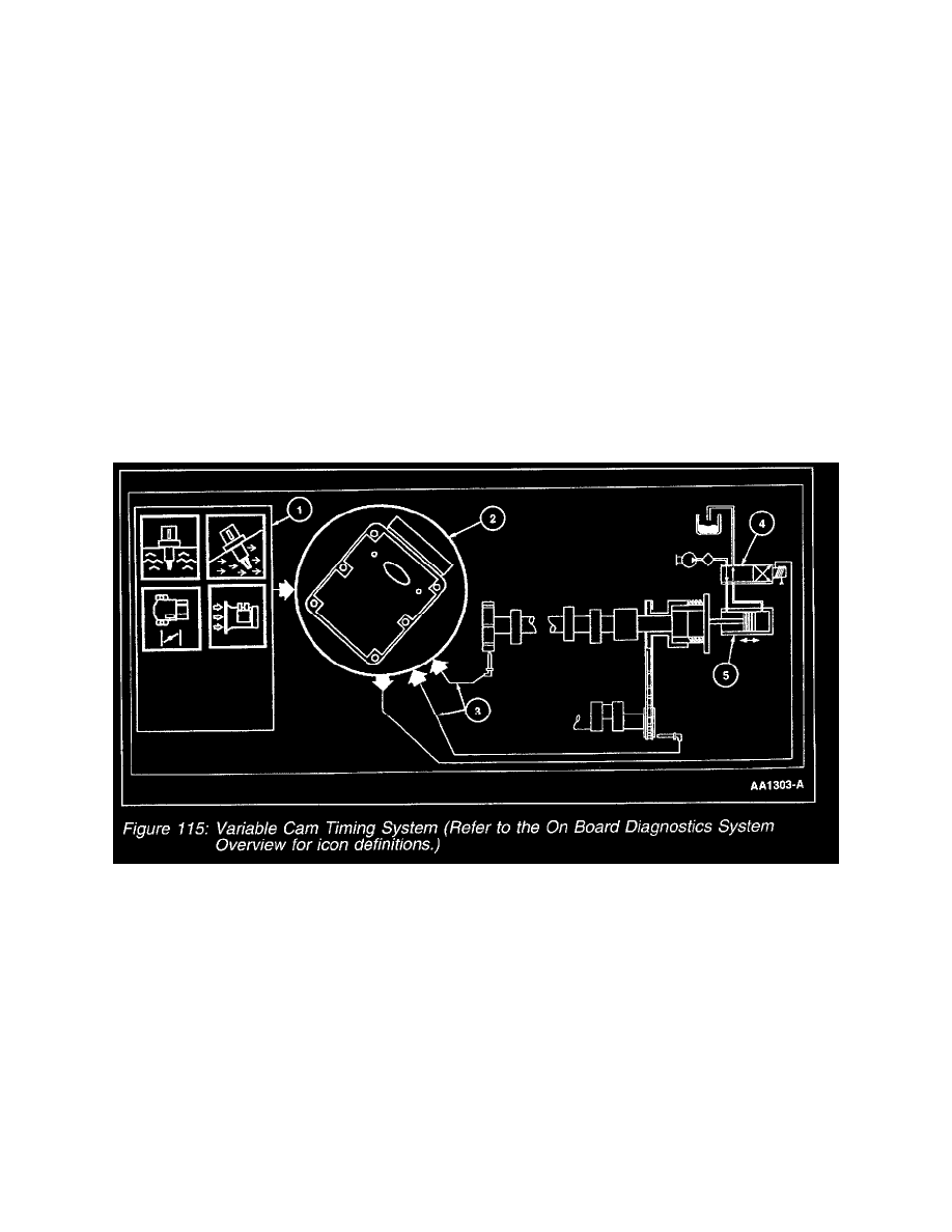
The VCT (variable cam timing) system consists of an electric hydraulic positioning control solenoid, a CMP (camshaft position sensor) and trigger
wheel. The CMP trigger wheel has a number of equally spaced teeth equal to the number (n) of cylinders on a bank plus one extra tooth (n+1). Four
cylinder and V8 engines use a CMP 4+1 tooth trigger wheel. V6 engines use a CMP 3+1 tooth trigger wheel. The extra tooth placed between the
equally spaced teeth represents the CMP signal for that bank. A CKP (crankshaft position sensor) provides the PCM with crankshaft positioning
information in 10 degree increments (Figure 115).
1. The PCM receives input signals from the IAT (intake air temperature), ECT (engine coolant temperature), EOT (engine oil temperature), CMP,
TP (throttle position), MAF (mass air flow) and CKP to determine the operating conditions of the engine. At idle (low engine speeds and closed
throttle) the PCM controls camshaft position based on air and coolant temperatures. During part and wide open throttle, camshaft position is
determined by engine RPM, load and throttle position. The VCT system will not operate until the engine is at normal operating temperature.
2. The VCT system is enabled by the PCM when the proper conditions are met.
3. The CKP signal is used as a reference for CMP positioning.
4. The VCT solenoid valve is an integral part of the VCT system. The solenoid valve controls the flow of engine oil in the VCT actuator assembly.
As the PCM controls the duty cycle of the solenoid valve, oil pressure/flow advances or retards the cam timing. Duty cycles near 0% or 100%
represent rapid movement of the camshaft. Retaining a fixed camshaft position is accomplished by dithering (oscillating) the solenoid valve duty