
E 150 V8-4.6L SOHC VIN W (2004)
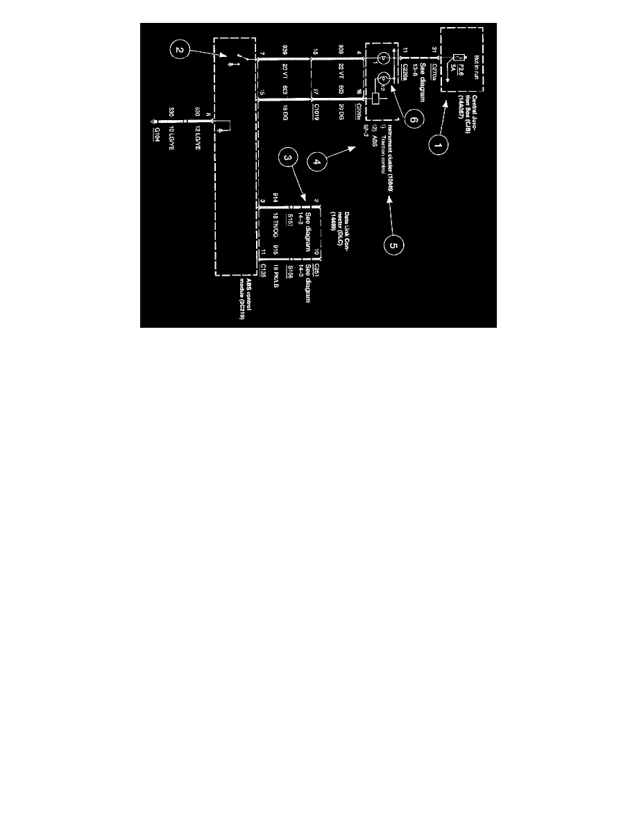
Current Flow (1)
Each set of diagrams normally starts with the component that powers the circuit such as a fuse or the ignition switch. Current flow is shown from the
power source at the top of the diagram to ground at the bottom of the diagram. In order to concentrate on the essential parts, power supply and ground
connections are sometimes simplified by a dashed line in the diagrams. A full representation of the power supply of a fuse or the power distribution
from a fuse to various components is given in the Power and Ground Distribution Diagrams. Full representation of the ground connections are shown
in the Power and Ground Distribution Diagrams.
Switch Positions (2)
Within the diagram, all switches, sensors and relays are shown "at rest" (as if the Ignition Switch were OFF).
Splices (3)
A dashed line indicates that the splice is not shown completely. A reference is given to the diagram where the splice appears in full.
Component Referencing (4)
Each component on a diagram has a reference to the component location view for that component (i.e. 151-1, 151-10, etc.). These view references are
located to the right of each component shown in a diagram. The views themselves can be found at Vehicle Locations.
Component Names, Notes and Base Part Numbers (5)
Component names are placed on the right hand side of each component. Any notes that describe switch positions or operating conditions follow the
name. Descriptions of the internals of the component are also included here. The base part number for a component is listed in parentheses next to or
under a component.
Internal Name and Function ID Numbers (6)
Some components on each diagram have internal symbols with an identification number located to the right. You can identify the internal symbol or
function by finding the corresponding number under the component name.