
E 150 1/2 Ton Van V6-4.2L VIN 2 (1997)
Control Assembly: Description and Operation
Control Components
Control System Inputs
The climate control system inputs are selected manually from the climate control head.
Control System Outputs
AIR MANAGEMENT DOORS
The air management doors are controlled by vacuum control motors, a vacuum control motor and an A/C electronic door actuator motor. The air
inlet and distribution doors are controlled by a vacuum control motor. The temperature blend door is controlled by the A/C electronic door
actuator motor.
The A/C electronic door actuator motor provides a variable number of temperature blend door positions. The temperature control position
energizes the A/C electronic door actuator motor, moving the temperature blend door.
Vacuum control motors are used on both air distribution and air inlet doors. The air inlet and panel doors use two-position vacuum control motors.
The floor duct/defrost door uses a three-position vacuum control motor. Vacuum control motors are controlled by engine vacuum through the
climate control head.
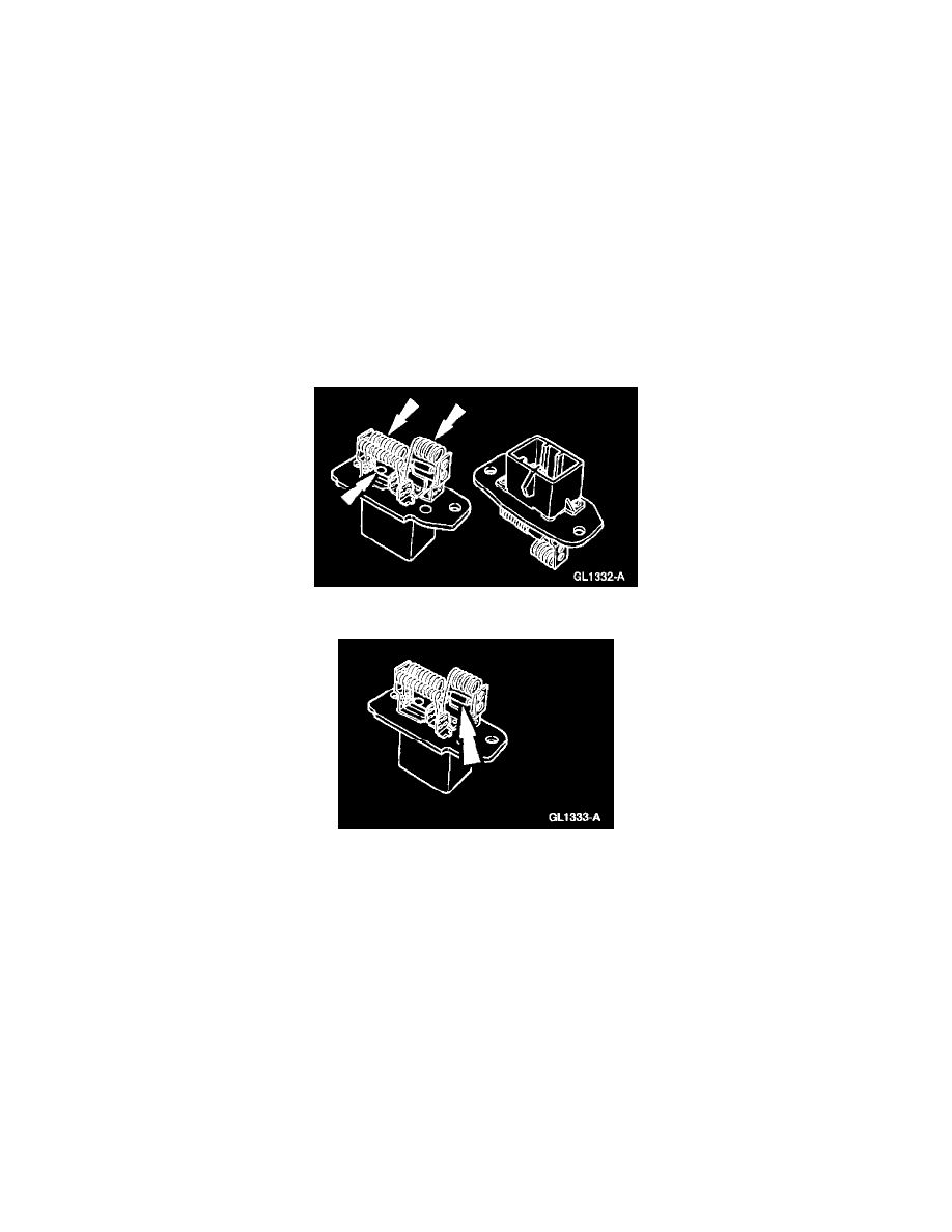
Blower Motor Resistor Coils
Blower Motor Thermal Limiter
BLOWER MOTOR CIRCUIT
The blower motor circuit consists of a blower motor switch, a heater blower motor switch resistor with a thermal limiter and the blower motor.
Blower motor speed is determined by changing the current flow to the blower motor using resistor coils. The blower motor switch has four speeds
that are obtained using three resistor coils that are wired in series. The heater blower motor switch resistor is wired into the blower motor ground
circuit.
^
High Speed - Current through the blower motor bypasses all resistor coils and travels directly to ground.
^
Medium High Speed - Current travels through one resistor coil and then to ground, reducing current flow and blower motor speed.
^
Medium Low Speed - Current travels through two resistor coils, reducing current flow and blower motor speed.
^
Low Speed - Current flow travels through all three resistor coils, adding the highest resistance causing the blower motor to run at its slowest
speed.
The thermal limiter is integral to the heater blower motor switch resistor and serves as a temperature protection device. The thermal limiter is
wired in series with the heater blower motor switch resistor coils and opens when the resistor coils reach approximately 300°F (121°C). When the
thermal limiter opens, the blower motor will only operate when the heater blower motor switch is set to HIGH speed. The thermal limiter does not
reset once opened. The heater blower motor switch resistor must then be replaced.
Manual Climate Control System