
E 250 V8-4.6L VIN W (2006)
While turning the rotor clockwise, carefully feel for the ribbon wire to run out of length and for a slight resistance. Stop turning at this point.
3
Turn the clockspring counterclockwise approximately 2.25 turns. This is the center point of the clockspring.
-
Do not allow the rotor to turn from this position.
Vehicle repairs reusing the same clockspring
3. NOTE: When the tape is removed, do not allow the clockspring to turn.
Remove the tape applied during clockspring removal.
All vehicles
4. NOTE: Slight turning of the clockspring rotor is allowable for alignment purposes to the steering column.
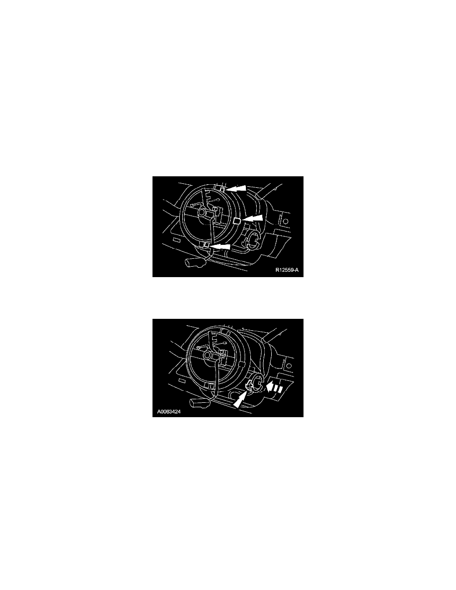
With the flats of the clockspring rotor aligned to the flats of the steering column shaft, slide the clockspring onto the steering column engaging the
retaining tabs.
5. Press at the 6, 12 and 3'o clock positions to seat the clockspring.
6. Route the clockspring wiring through the instrument panel.
7. Attach the 2 clockspring retaining clips holding the wire to the steering column.
8. If equipped, install the key-in-ignition warning indicator switch.
9. Install the upper steering column shroud.
10. Install the lower steering shroud and the 3 screws.
11. Install the ignition switch lock cylinder.
-
Position the ignition switch lock cylinder to the RUN position.
-
Insert the ignition switch lock cylinder into the steering column housing.
-
Make sure the ignition switch lock cylinder is fully seated and aligned in the inter-locking washer before turning the key to the OFF position.
This will permit the retaining pin of the ignition switch lock cylinder to extend into the hole in the steering column.
12. Rotate the ignition switch lock cylinder, using the key, to make sure of correct mechanical operation in all positions.
13. If equipped, install the tilt wheel shank handle.
14. Install the steering wheel.
15. Connect the clockspring electrical connectors.
-
Install the pin-type retainers into the bracket.
16. Install the steering column opening lower finish panel reinforcement and the 6 bolts.
17. Install the 2 screws and the data link connector.