
E 250 V8-5.4L (2008)
4. CAUTION: Do not allow the camber adjustment sleeve to contact the ball joint seal when installing a sleeve or damage to the ball joint
seal may occur. Allow for a minimum of 2 mm (0.079 inch) clearance between the camber adjustment sleeve and the ball joint seal.
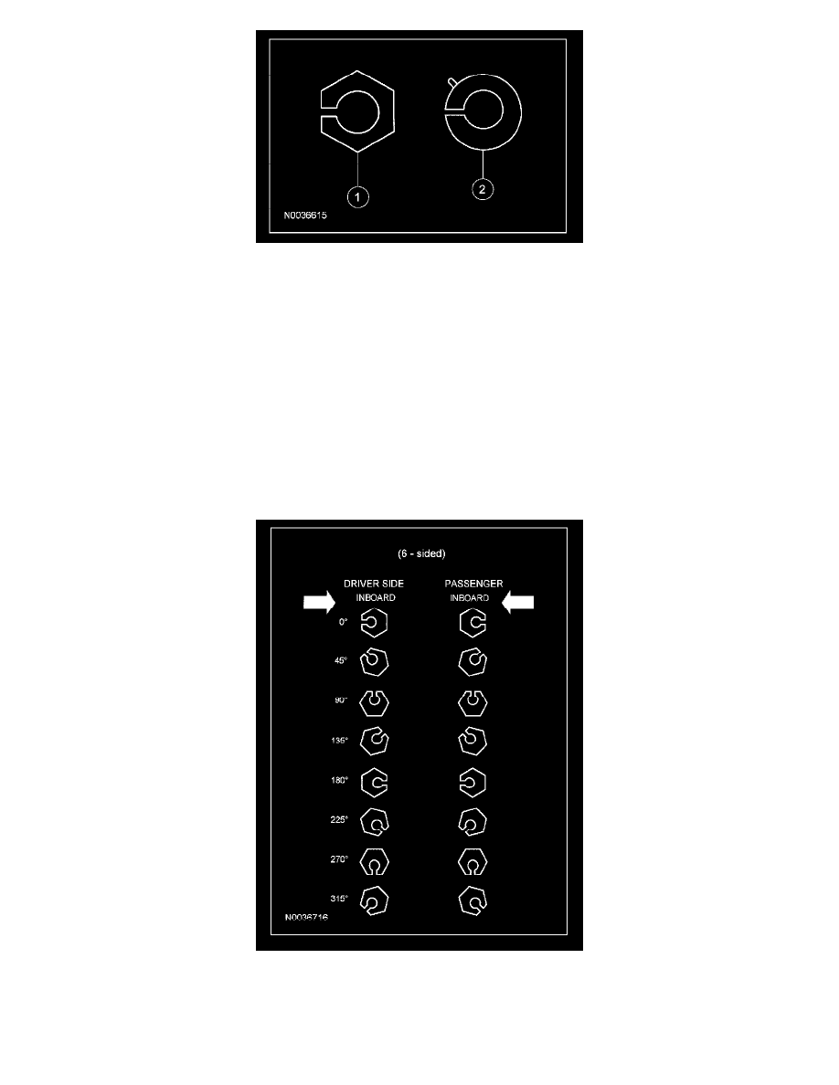
Install interim 0 degree service adjusters to both sides of the vehicle.
5. Install the upper ball joint pinch bolt.
^
Tighten to 103 Nm (76 lb-ft).
6. Install the front wheel(s) and check caster and camber readings with the 0 degree service adjusters installed.
7. Calculate the maximum amount of camber and/or caster adjustment required to achieve the optimal settings, as provided in the Alignment
Specifications table, by subtracting the measured values from the optimal target values.
Example: for an E-150,
^
Optimal camber spec target = 0.5 ± 0.75
^
Optimal caster LH spec target = 4.1 ± 2.75.
^
Measured camber = 1.80 (out-of-spec).
^
Measured caster = 3.3 (within spec).
^
Required camber adjustment = 0.5 - 1.80 = -1.3.
^
Preferred caster adjustment = 4.1 - 3.3 = 0.8, however not required.
8. Using the Camber/Caster Service Adjuster table, determine the appropriate replacement service adjuster needed to correct alignment. There is
usually more than one combination of service adjuster and orientation that can be chosen to achieve alignment measurements within specifications.
If a compromise is required, choose the adjuster and orientation which optimizes the camber value and maximizes the caster value.
Example: continuing the above example,