E 250 Van L6-300 4.9L (1984)

7.
Lower the vehicle.
8.
Check the idle and hi-cam speeds and reset to the decal specifications, if necessary.
NOTE:
The customer should retain the removed PCV valve and re-install it If the vehicle is returned to sea level operation. The new transmission
diaphragm is self-compensating for both sea level and altitude and does not need to be removed.
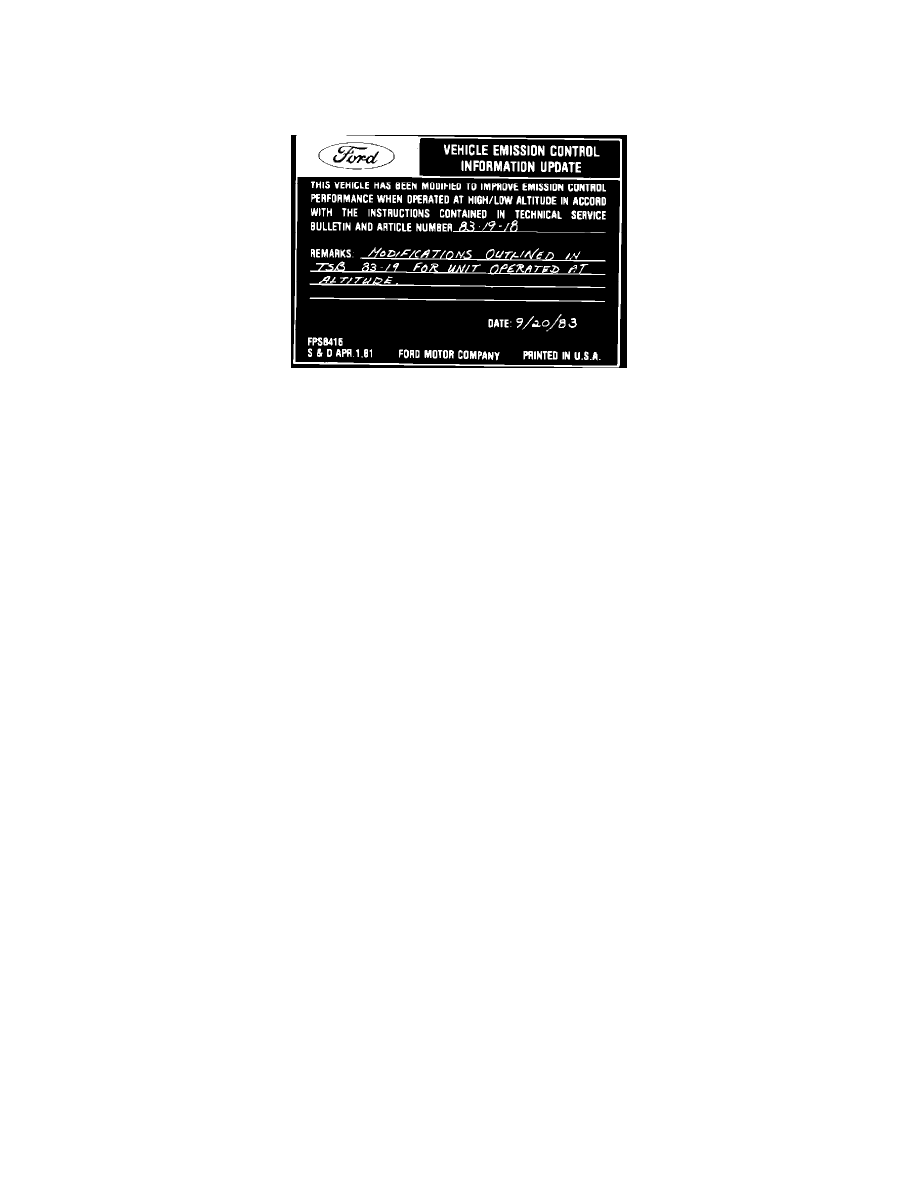
Obtain an Authorized Modifications decal and list the date, dealer number and summary of alterations performed. Select a prominent place adjacent to
the Vehicle Emission Control Information decal suitable for installing the Authorized Modifications decal. Clean the area, install the decal and cover it
with a clear plastic decal shield.
PART NUMBER
PART NAME
CLASS
DBTZ-6A666-A
PCV Valve
A
D8AZ-7A377-A
Altitude Compensating
AM
Diaphragm
OTHER APPLICABLE ARTICLES: None
WARRANTY STATUS: Reimbursable within the provisions of the Warranty and Policy Manual.
OPERATION: M
TIME:
"Actual Time" as defined in the Warranty and Policy Manual. DLR. CODING: Basic Part No. DRIVE Code: H7
Technical Service Bulletin # 851622
Date: 850814
Carburetor - Rough Engine Idle
Article No. 85-16-22
IDLE - ROUGH (4.9L) - VEHICLES UNDER 8500 LBS. GVW
LIGHT TRUCK 1984-85 E, F SERIES, BRONCO
CALIBRATIONS: 4-51 D, E, F, H, K, L, R, S, T, Z 4-52G, L, R, S, T, W 5-51D, E, F, H, K, L, V, Z 5-52E, F, H, K, M, W, Y
WARNING:
This modification is authorized only for the listed engines. Performing this modification on other engine calibrations is unauthorized and
could create liability under applicable federal or local laws.
A rough idle could be due to a variety of conditions. Diagnostic procedures for this concern are:
1.
Ensure that initial timing is to specification and that no vacuum leak exists.
2.
Ensure that curb idle is to specification. If the curb idle speed is out of specification by more than 50 RPM, refer to Emission Diagnostic Manual
(Volume H), for reset procedure of the idle speed control motor.
3.
Inspect the fuel inlet needle. If it is damaged or if the tip material is black, install the latest design fuel inlet needle and seat assembly
E4PZ-9564-A. The new needle, which has a pink tip, is resistant to alcohol and contaminated fuel.
4.
Reset the float level as described on Page 24-06-6 of the 1985 Light Truck Shop Manual. However, for vehicles that consistently operate above
2000 feet altitude, use a 0.810 inch float level gauge instead of the 0.780 gauge specified. A 13/16 inch drill can be used as a float level gauge
above 2000 feet altitude, and a 25/32 inch drill can be used at lower altitudes. When using a drill, be careful to measure only to the identation on
the float.
5.
If the above steps do not resolve the concern, reset the idle mixture using the propane enrichment method outlined in TSB 85-1-23. However, if a
reset is necessary (Step IIE of the TSB), use a reset of 10 RPM instead of the 30 RPM specified.
