
E 250 Van V8-351 5.8L (1982)
Knock Sensor: Testing and Inspection
Component Testing
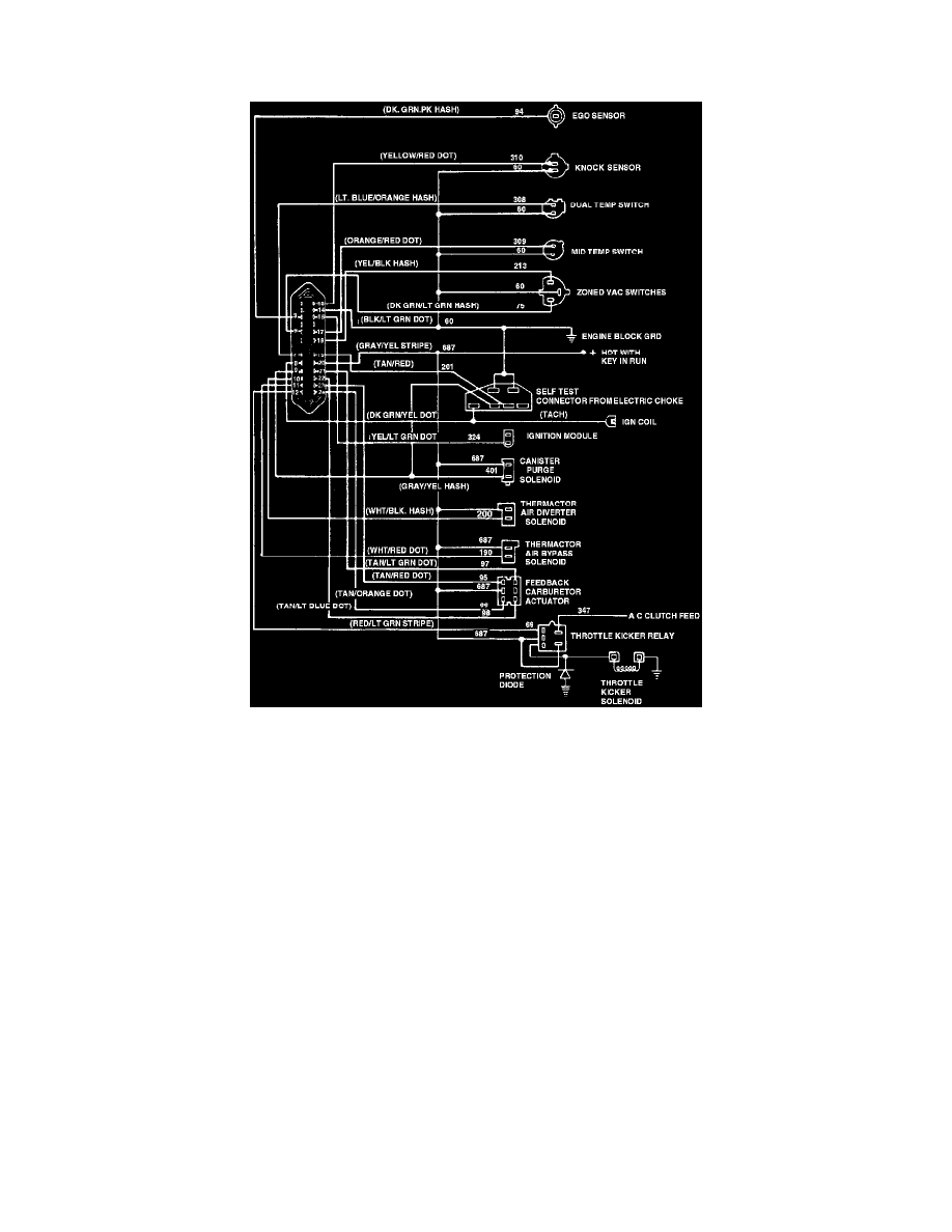
Fig.8 - MCU System Wiring Circuit
1. Make sure that the following three steps are properly conducted in order to simulate spark knock conditions and determine that spark detection
system is inoperative. If not, repeat test to verify problem.
a. Make sure that engine is at normal operating temperature. Run engine at 2000 rpm for 2 minutes, then turn key off. Immediately restart engine
and allow to idle.
b. Observe voltmeter and vacuum gauge for initialization pulses after restarting the engine. The throttle kicker will also extend (increase engine
speed) and remain on throughout the test.
c. On vehicles with spark knock sensor, when initial pulses occur, immediately simulate spark knock by placing a 3/8 inch extension on manifold
near base of knock sensor. Tap end of extension with a small hammer for about 15 seconds.
2. Disconnect jumper wire from self-test trigger input circuit 201.
3. With ignition key off, disconnect vehicle harness from spark knock sensor.
4. Using a torque wrench and a 1 1/8 inch deep socket, make sure that spark sensor is torqued to 12-18 ft. lbs. If sensor is properly torqued, proceed
to next step. If not, torque to specifications.
5. Disconnect vehicle harness from MCU and spark sensor. Connect one lead of an ohmmeter to circuit 310 of vehicle harness and other lead to
engine block, Fig. 8. If resistance is 1000 ohms or more, proceed to next step. If resistance is less than 1000 ohms, repair short to ground in circuit
301.
6. With key off and knock sensor harness disconnected, check circuit 310 of vehicle harness for continuity. If resistance is 10 ohms or less, continue
to next step. If resistance is greater than 10 ohms, repair circuit 310.
7. Check circuit 60 of vehicle harness for continuity between knock sensor and MCU, Fig. 8. If resistance is 10 ohms or less, reconnect harness
connector to MCU and proceed to next step. If resistance is greater than 10 ohms, service circuit 60.
8. Reconnect jumper wire to circuits 201 and 60 of VIP connector, Fig. 8.
9. Connect a test lamp to positive terminal of battery, then disconnect knock sensor from vehicle harness.
10. Perform "Engine Running Functional Test" procedure. When the four initialization pulses occur, continuously tap circuit 310 of the vehicle
harness connector, which mates to the knock sensor connector, with the probe end for 5 seconds while observing voltmeter pulses. If a code 25 is