
E 250 Van V8-7.3L DSL (1988)
20.
Remove lock bearing snap ring, then the lock bearing.
21.
Remove lock drive gear through lock cylinder opening, then the lock actuator assembly and lock actuator insert.
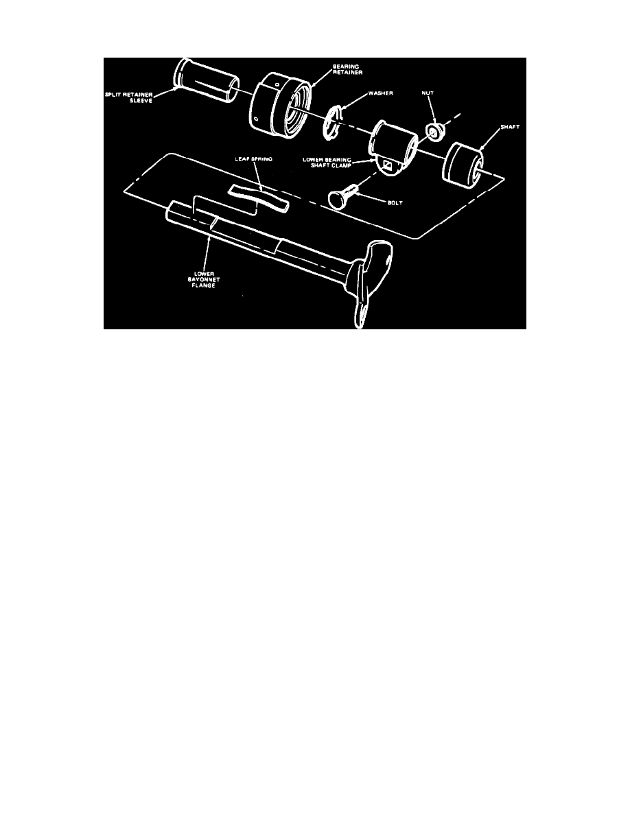
Fig. 11 Lower Bearing Retainer
22.
On E-Series, disassemble steering column lower bearing retainer subassembly as follows:
a.
Remove steering column lower bayonet flange and leaf spring, Fig. 11. Do not loosen leaf spring.
b.
Remove lower bearing shaft clamp, bolt, and nut.
c.
Remove three screws and the lower bearing assembly.
d.
Remove split retainer sleeve from lower bearing retainer assembly.
23.
On vehicles equipped with three speed manual transmission, disassemble shift tube subassembly as follows:
a.
Hold shift tube above spring and push up and rotate lower shift arm until loading slot in arm aligns with lower key.
b.
Remove lower arm and lower spacer.
c.
Rotate upper shift arm until loading slot in arm aligns with lower key, then remove upper arm and upper spacer.
d.
Remove and discard shift arm grommets.
ASSEMBLY
1.
On vehicles equipped with three speed manual transmission, place bushing in socket retainer in outer tube.
2.
On vehicles equipped with three speed manual transmission, place bushing on upper hub and wave washer on lower hub of shift socket.
3.
On vehicles equipped with three speed manual or automatic transmission, install shift socket in outer tube.
4.
On vehicles equipped with four speed manual transmission, install flange extension on outer tube.
5.
On all models, install lock actuator insert in rear of flange and torque screw to 15-25 inch lbs.
6.
Insert lock actuator assembly through opening in front of flange until it bottoms against insert.
7.
Install lock drive gear through lock cylinder opening so that last gear tooth aligns with last tooth on actuator assembly when actuator is fully
rearward.
8.
Install lock bearing, then the lock bearing snap ring.
9.
Place lock cylinder in On position and depress retaining pin, then insert lock cylinder into flange.
10.
On vehicles equipped with automatic transmission, attach PRNDL21 insert to front of flange.
11.
On vehicles equipped with manual transmission, position spring on lock release lever assembly and position lever assembly through hole in
front of flange, then tighten spring until lever assembly drops into place.
12.
On vehicles equipped with manual transmission, install snap ring on lock release lever assembly.
13.
On all vehicles, install flange retaining bolts through holes in flange and hand start nuts 1 to 2 threads.
14.
On vehicles equipped with automatic transmission, place wave washer in flange hub.
15.
On all models, install subassembled flange onto outer tube by pinching nuts toward each other and pressing flange in place, then torque nuts to
60-75 inch lbs.
16.
On vehicles equipped with three speed manual transmission, assemble shift tube assembly as follows:
a.
Install grommets in shift tube, small end facing up.
b.
Stack upper spacer, upper arm, lower spacer, and lower arm concentrically in order so that loading slots align.
c.
Press entire stack through common loading slot on shift tube, then rotate stack components individually until arms are aligned with their
keyways on shift key and spacers allow shift key to pass freely through operating slots.
17.
On vehicles with three speed manual transmission, load shift tube assembly through lower opening of column.