
E 250 Van V8-7.3L DSL (1988)
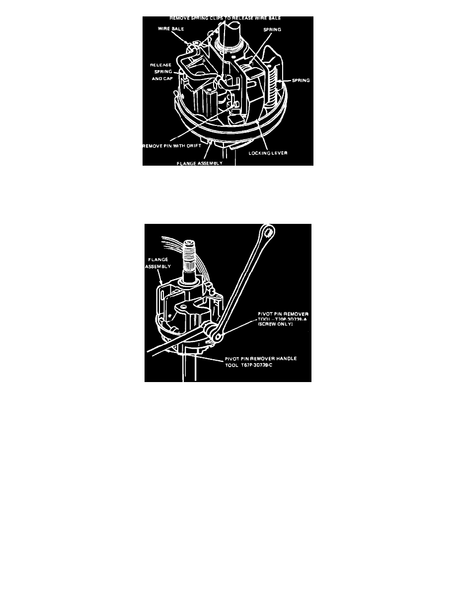
Fig. 4 Removing Wire Bale And Tilt Locking Lever
16.
On all models, remove flange extension, then remove spring clips holding wire bale, then bale, Fig. 4.
17.
Drive out pin holding locking lever, then remove the lever and spring.
18.
Remove column upper shaft snap ring.
Fig. 5 Removing Flange assembly Pivot pins
10 C19.
Using pivot pin remover tool and handle tool Nos. T70P-3D739-A and T67P-3D739-C or equivalents, remove two pivot pins from side of casting
assembly, then separate upper and lower flange castings, Fig. 5. If pivot pins fit loosely in the lower flange, the pins must be discarded.
20.
Position flange casting on suitable workbench with smaller bearing facing down.
21.
Lightly tap on outer race of small bearing at each slot, using a small drift, and remove race and bearing.
22.
Invert flange casting and repeat step 22 on large bearing.
ASSEMBLY
1.
Position flange casting on suitable workbench with large bearing seat facing up.
2.
Place large upper bearing over seat with open side facing inward. Position a suitable socket on bearing outer race and lightly tap socket until
bearing is seated. Use care to avoid contacting bearing inner race as damage will result.
3.
Invert flange casting and repeat step 2 on small bearing.
4.
Install lower actuator with ignition switch rod attached.
5.
Install upper and lower flanges with pivot pins. Ensure column position spring is seated properly between upper and lower flange and wavy thrust
washer is properly positioned between lower flange and socket. Do not reuse loose pivot pins.
6.
Install column upper shaft snap ring.
7.
Install locking lever, spring and lever pin.