
E 350 V10-6.8L (2007)
G7-G12
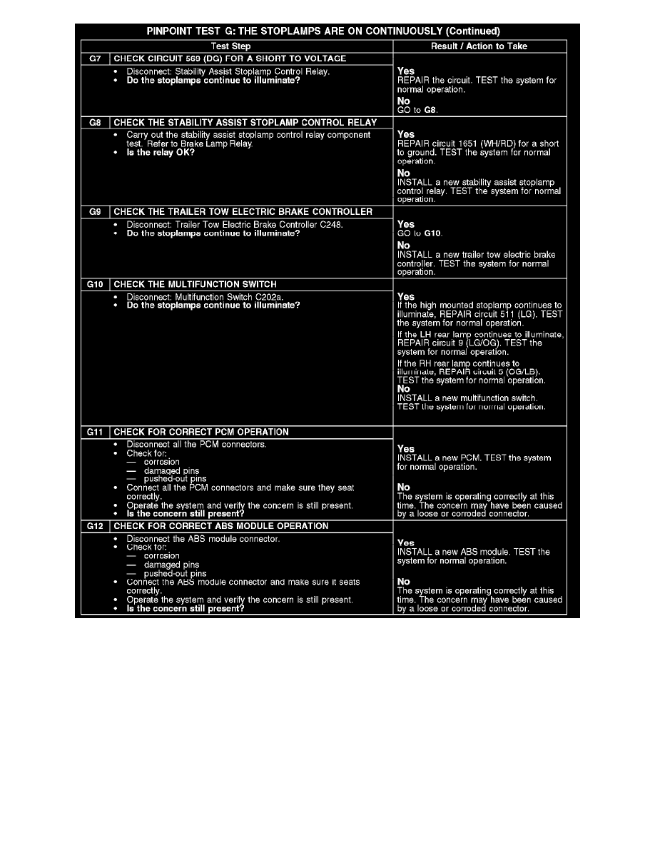
Normal Operation
When the brake pedal is applied, the stoplamp switch routes voltage through circuit 569 (DG) to the brake shift interlock actuator, the anti-lock brake
system (ABS) module (without stability assist), the powertrain control module (PCM), and the central junction box (CJB) fuse 39 (10A). The CJB
then routes the voltage through circuit 511 (LG) to the high mounted stoplamp, the trailer tow electric brake controller (if equipped), and the
multifunction switch. The multifunction switch then routes voltage to the rear lamps through circuit 9 (LG/OG) (LH rear lamp) and circuit 5 (OG/LB)
(RH rear lamp).
On vehicles equipped with stability assist, the ABS module controls a relay which, when energized, routes voltage to circuit 569 (DG).
Possible Causes
-
Circuit 5 (OG/LB short to voltage
-
Circuit 9 (LG/OG) short to voltage
-
Circuit 511 (LG) short to voltage