
E 350 V10-6.8L VIN S (2006)
F4-F5
Normal Operation
When the brake pedal is applied, voltage is routed from the central junction box (CJB) through circuit 511 (LG). Circuit 511 (LG) supplies voltage to
the high mounted stoplamp and the multifunction switch. The multifunction switch then routes the voltage to the rear lamps through circuit 9 (LG/OG)
(LH rear lamp) and circuit 5 (OG/LB) (RH rear lamp). The stoplamps share a common ground through circuit 57 (BK).
Possible Causes
-
Circuit 5 (OG/LB) open
-
Circuit 9 (LG/OG) open
-
Circuit 57 (BK) open
-
Circuit 511 (LG) open
-
Multifunction switch
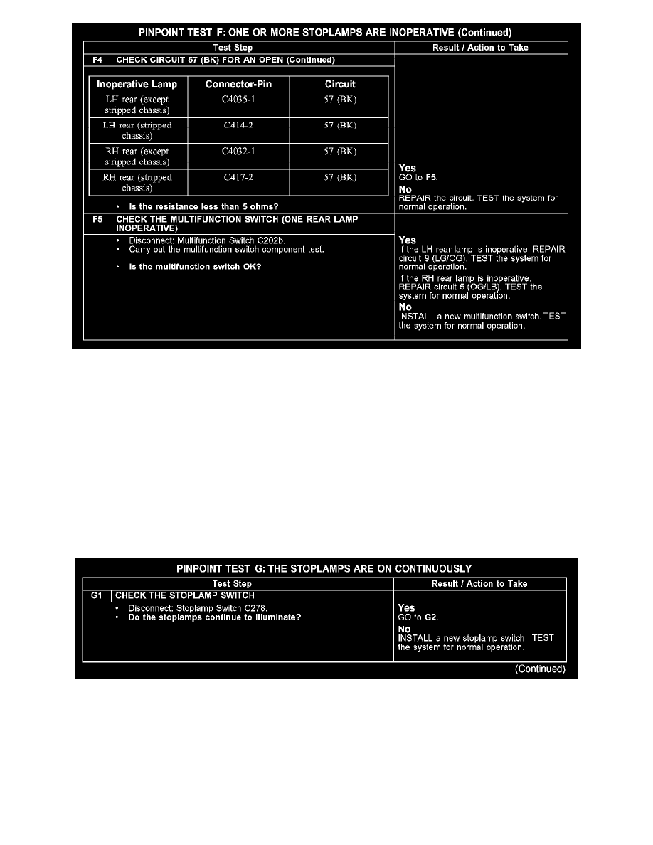
Test G: The Stoplamps Are On Continuously
PINPOINT TEST G: THE STOPLAMPS ARE ON CONTINUOUSLY
G1