
E 350 V10-6.8L VIN S (2006)
This will reduce the risk of injury in the event of an accidental deployment.
-
To reduce the risk of personal injury, do not use any memory saver devices.
NOTE:
-
The air bag warning lamp illuminates when the RCM fuse is removed and the ignition switch is ON. This is normal operation and does not indicate
a supplemental restraint system (SRS) fault.
-
The SRS must be fully operational and free of faults before releasing the vehicle to the customer.
-
Repair is made by installing a new part only. If the new part does not correct the condition, install the original part and carry out the diagnostic
procedure again.
1. Depower the system. See: Air Bag(s) Arming and Disarming/Service and Repair
2. Remove the driver air bag module.
3. Pull to release the retaining clips and remove the steering column opening lower finish panel.
4. On the steering column opening lower finish panel reinforcement, detach the pin-type retainer and remove the electrical connector.
5. On the steering column opening lower finish panel reinforcement, remove the 2 screws and the data link connector.
6. Remove the 6 bolts and the steering column opening lower finish panel reinforcement.
7. Disconnect the clockspring electrical connectors at the base of the steering column and detach the connectors from the bracket.
8. NOTE: Make sure the road wheels are in the straight-ahead position.
Remove the steering wheel.
9. If equipped, loosen the tilt wheel shank handle and remove.
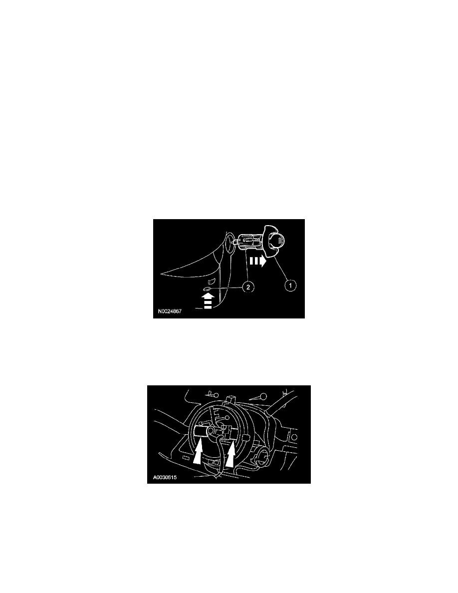
10. Remove the ignition switch lock cylinder.
1
Position the lock cylinder to RUN.
2
Using a suitable tool, push upward on the cylinder release tab through the hole in the lower shroud while pulling the cylinder outward.
11. Remove the 3 screws and the lower steering column shroud.
12. Remove the upper steering column shroud.
13. NOTE: If the clockspring is to be reinstalled, do not allow the clockspring to turn from its removal position.
If reusing the clockspring, tape the clockspring center rotor to the outer housing to keep it from rotating.