
E 350 V8-5.4L (2008)
5. Tighten the RH rear brake caliper bleeder screw to 11 Nm (8 lb-ft), remove the rubber hose and install the bleeder screw cap.
6. Repeat Steps 2 through 5 for the LH rear brake caliper bleeder screw.
^
Tighten the LH rear brake caliper bleeder screw to 11 Nm (8 lb-ft).
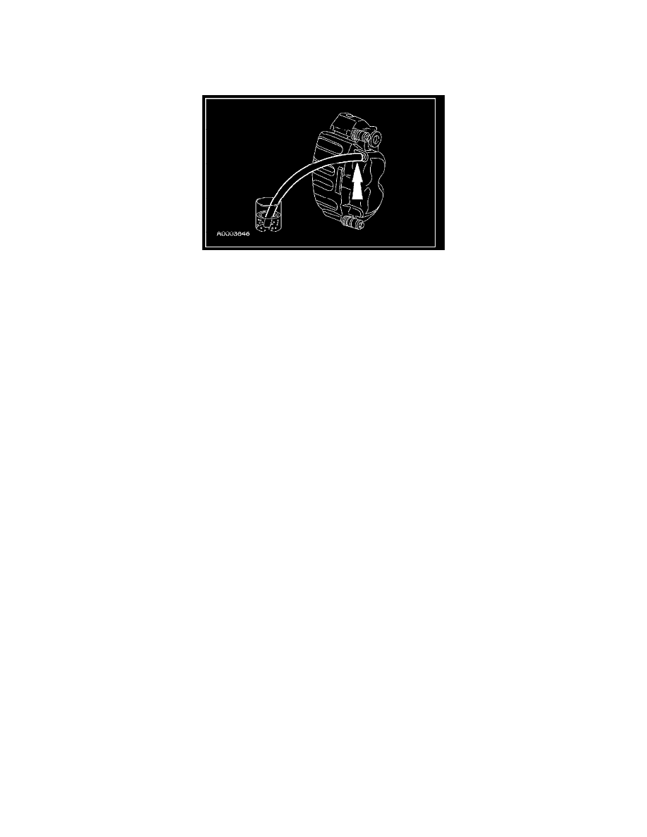
7. Remove the RH front brake caliper bleeder screw cap and place a box-end wrench on the bleeder screw. Attach a rubber drain hose to the bleeder
screw and submerge the free end of the hose in a container partially filled with clean, specified brake fluid.
8. Have an assistant pump the brake pedal and then hold firm pressure on the brake pedal.
9. Loosen the RH front brake caliper bleeder screw until a stream of brake fluid comes out. While the assistant maintains pressure on the brake pedal,
tighten the bleeder screw.
^
Repeat until clear, bubble-free fluid comes out.
^
Refill the brake master cylinder reservoir as necessary.
10. Tighten the RH front brake caliper bleeder screw to 15 Nm (11 lb-ft), remove the rubber hose and install the bleeder screw cap.
11. Repeat Steps 7 through 10 for the LH front brake caliper bleeder screw.
^
Tighten the LH front brake caliper bleeder screw to 15 Nm (11 lb-ft).
ABS Hydraulic Control Unit (HCU) Bleeding
WARNING: Do not use any fluid other than clean brake fluid meeting manufacturer's specification. Additionally, do not use brake fluid that
has been previously drained. Following these instructions will help prevent system contamination, brake component damage and the risk of
serious personal injury.
WARNING: Carefully read cautionary information on product label. For EMERGENCY MEDICAL INFORMATION seek medical advice.
In the USA or Canada on Ford/Motorcraft products call: 1-800-959-3673. For additional information, consult the product Material Safety
Data Sheet (MSDS) if available. Failure to follow these instructions may result in serious personal injury.
WARNING: Do not allow the brake master cylinder to run dry during the bleeding operation. Master cylinder may be damaged if operated
without fluid, resulting in degraded braking performance. Failure to follow this instruction may result in serious personal injury.
CAUTION: Brake fluid is harmful to painted and plastic surfaces. If brake fluid is spilled onto a painted or plastic surface, immediately wash
it with water.
NOTE: When the hydraulic control unit (HCU) or master cylinder is disconnected for repair or installation of new components, air can get into the
system and cause spongy brake pedal action. This requires bleeding of the hydraulic system after it is correctly connected. The hydraulic system can
be bled manually or with pressure bleeding equipment.
NOTE: This procedure is only required when a new HCU is installed.
1. NOTE: Carrying out the System Bleed function drives trapped air from the HCU. Subsequent bleeding removes the air from the brake hydraulic
system through the bleeder screws.
NOTE: Adequate voltage to the HCU module is required during the anti-lock control portion of the system bleed.
Connect the scan tool to the vehicle.
2. Access the ABS HCU bleed function and follow the directions on the scan tool.
3. Manually bleed the brake hydraulic system.
4. Repeat the procedure carrying out a total of 2 scan tool cycles and 2 manual bleed cycles.