
E 350 V8-5.4L (2008)
Electronic Throttle Control Module: Description and Operation
TORQUE BASED ELECTRONIC THROTTLE CONTROL (ETC)
Overview
The torque based ETC is a hardware and software strategy that delivers an engine output torque (via throttle angle) based on driver demand (pedal
position). It uses an electronic throttle body, the powertrain control module (PCM), and an accelerator pedal assembly to control the throttle opening
and engine torque.
Torque based ETC enables aggressive automatic transmission shift schedules (earlier upshifts and later downshifts). This is possible by adjusting the
throttle angle to achieve the same wheel torque during shifts, and by calculating this desired torque, the system prevents engine lugging (low RPM and
low manifold vacuum) while still delivering the performance and torque requested by the driver. It also enables many fuel economy/emission
improvement technologies such as variable camshaft timing (VCT) (deliver same torque during transitions).
Torque based ETC also results in less intrusive vehicle and engine speed limiting, along with smoother traction control.
Other benefits of ETC are:
-
eliminate cruise control actuators
-
eliminate idle air control (IAC) valve
-
better airflow range
-
packaging (no cable)
-
more responsive powertrain at altitude and improved shift quality
The ETC system illuminates a powertrain malfunction indicator (wrench) on the instrument cluster when a concern is present. Concerns are
accompanied by diagnostic trouble codes (DTCs) and may also illuminate the malfunction indicator lamp (MIL).
Electronic Throttle Body (ETB)
The ETB has the following characteristics:
-
The throttle actuator control (TAC) motor is a DC motor controlled by the PCM (requires 2-wires).
-
There are 2 designs: parallel and in-line. The parallel design has the motor under the bore parallel to the plate shaft. The motor housing is
integrated into the main housing. The in-line design has a separate motor housing.
-
An internal spring is used in both designs to return the throttle plate to a default position. The default position is typically a throttle angle of 7 to 8
degrees from the hard stop angle.
-
The closed throttle plate hard stop is used to prevent the throttle from binding in the bore (approximately 0.75 degree). This hard stop setting is
not adjustable and is set to result in less airflow than the minimum engine airflow required at idle.
-
The required idle airflow is provided by the plate angle in the throttle body assembly. This plate angle controls idle, idle quality, and eliminates the
need for an IAC valve.
-
There is 1 reference voltage and 1 signal return circuit between the PCM and the ETB. The reference voltage circuit and the signal return circuit is
shared with the reference voltage circuits and signal return circuits used by the APP sensor. There are also 2 TP signal circuits for redundancy.
The redundant TP signals are required for increased monitoring reasons. The first TP signal (TP1) has a negative slope (increasing angle,
decreasing voltage) and the second signal (TP2) has a positive slope (increasing angle, increasing voltage). The TP2 signal reaches a limit of
approximately 4.5 volts at approximately 45 degrees of throttle angle.
Accelerator Pedal Position (APP) Sensor
Depending on the application either a 2-track or 3-track APP sensor is used.
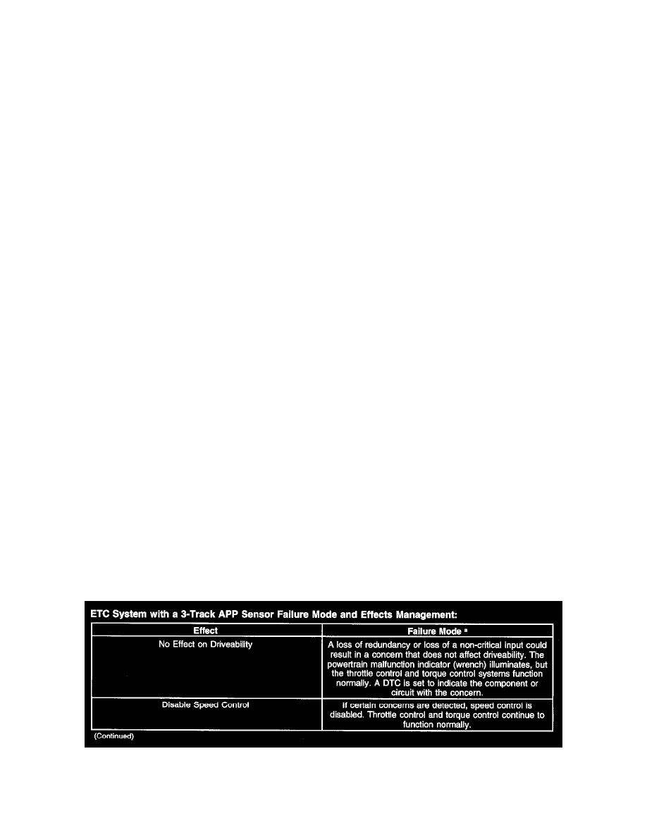
Electronic Throttle Control (ETC) System Strategy
ETC System With A 3-Track APP Sensor Failure Mode And Effects Management (Part 1)