
E 350 V8-5.4L (2008)
Ball Joint: Testing and Inspection
Ball Joint Inspection
1. Prior to inspecting the ball joints for wear, inspect the wheel bearings. Refer to Vehicle/Testing and Inspection.
2. Raise and support the vehicle by the frame or by the axle beams.
3. Inspect the ball joint and ball joint boot for damage.
^
If the ball joint or ball joint boot is damaged, install a new ball joint.
NOTE: Carry out Steps 4-6 to inspect the lower ball joint. Carry out Steps 7-9 to inspect the upper ball joint.
4. CAUTION: Do not use any tools or equipment to move the wheel and tire assembly or suspension components while checking for relative
movement. Suspension damage can occur. The use of tools or equipment will also create relative movement that may not exist when using
hand force. Relative movement must be measured using hand force only.
NOTE: To avoid lateral movement of the steering linkage and steering components, make sure to apply hand force only at the 12 o'clock and 6
o'clock positions of the wheel and tire assembly.
Inspect the ball joint for relative movement by alternately pulling outward and pushing inward on the wheel and tire assembly at the 12 o'clock and
6 o'clock positions, by hand. Note any relative movement between the wheel knuckle and the axle at the lower ball joint.
^
If relative movement is not felt or seen, the ball joint is OK. Do not install a new ball joint.
^
If relative movement is found, continue with Step 5.
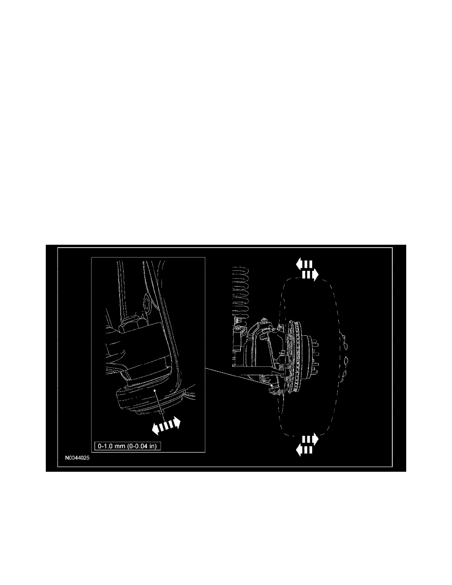
5. NOTE: The following illustrations are generic and may not represent the suspension design of the vehicle being tested.
NOTE: In order to obtain an accurate measurement, the dial indicator should be aligned as close as possible with the center line of the ball joint.
To measure ball joint deflection, attach a suitable dial indicator with a flexible arm between the axle and the wheel knuckle at the lower ball joint.
6. Measure the ball joint deflection while an assistant alternately pulls outward and pushes inward on the wheel and tire assembly at the 12 o'clock
and 6 o'clock positions, by hand.
^
If the deflection exceeds the specification, a new lower ball joint must be installed.
^
If the deflection meets the specification, continue with the procedure.
7. CAUTION: Do not use any tools or equipment to move the wheel and tire assembly or suspension components while checking for relative
movement. Suspension damage can occur. The use of tools or equipment will also create relative movement that may not exist when using
hand force. Relative movement must be measured using hand force only.
NOTE: To avoid lateral movement of the steering linkage and steering components, make sure to apply hand force only at the 12 o'clock and 6