
E 350 V8-6.0L DSL Turbo VIN P (2004)
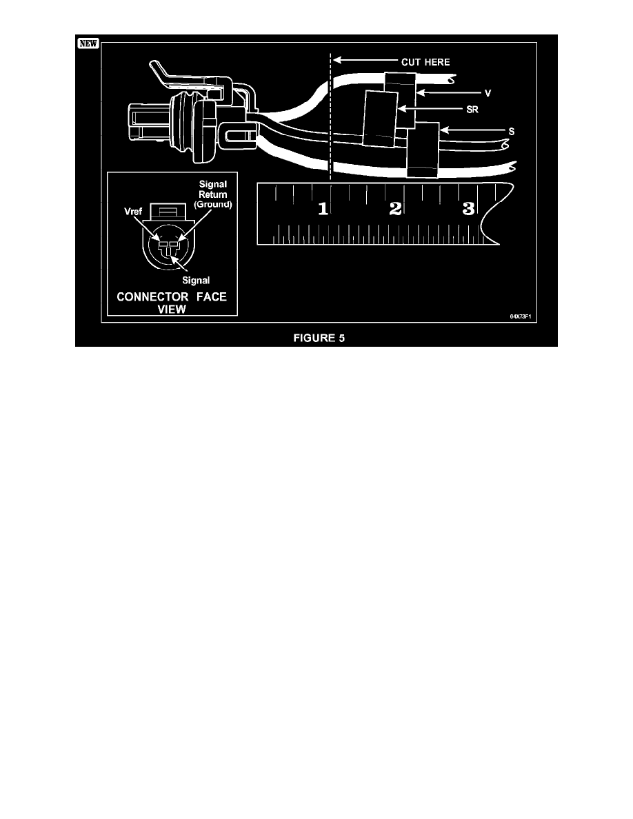
Identify each wire leading to the connector (Vref, Ground and Signal). Note the locations of each wire relative to the connector face view
provided. Place the identification tags at least a few inches away from the connector. See Figure 5.
4.
Cut the wires about 25 mm (1 inch) behind the connector on the vehicle harness MAKING SURE TO LEAVE THE IDENTIFYING TAGS ON
THE HARNESS and retain the old connector for reference. See Figure 5.
5.
Strip about 7 mm (1/4 inch) of insulation from the wires on the new pigtail.
6.
Using the crimp tool provided in the Rotunda Tool Kit, install the buff splice connectors provided in the service kit onto the replacement
connector pigtail.
7.
Strip about 7 mm (1/4 inch) of insulation from the wires on the vehicle harness.
8.
Position the heat shrink over the wires on the new connector.
9.
Matching the wires on the pigtail to the identifying tags on the vehicle harness, crimp the new butt connectors to the vehicle harness. Lightly tug
on the wires to make sure you have a good, tight splice.
10.
Position the heat shrink tubing over the butt splice connectors, then using the provided Flameless Heat Gun and deflector, heat the tubes on the
vehicle harness until they shrink and adhesive flows from the ends, indicating a water-tight seal.
11.
Fold the repaired harness to mirror the original harness length and tape the harness.
12.
Install a length of convolute over the spliced section of harness and secure with tape.
13.
Apply electrical grease to the face of the connector, forcing a small amount into all three (3) terminals.
[NEW]14. NOTE: The new connector is equipped with a new weather seal. Before connecting the ICP sensor, make sure the original weather seal is
not stuck on the sensor. If the original weather seal is left in place, it will impair connector attachment.
Connect the connector to the ICP sensor.
15.
Reinstall the generator. Refer to the procedure provided in this Attachment III.
GENERATOR INSTALLATION
1.
NOTE: Be sure to install the engine-to-body ground strap under the front stud bolt.