
Testing and Inspection of Companion Flange for E 350 V8-60L DSL Turbo VIN P (2004)
6. Align the holes on the Driveshaft Clamp Plate with the holes in the pinion flange and install the bolts. Snug the bolts evenly.
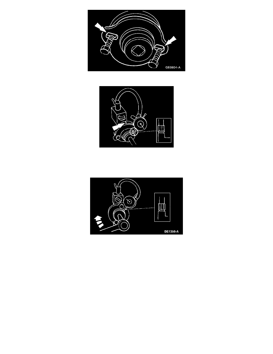
7. Position the Dial Indicator Gauge with Holding Fixture as shown. Turn the Drive Pinion Flange Runout Gauge, and locate and mark the high spot
on the companion flange with yellow paint.
If the flange runout exceeds 0.25 mm (0.010 inch), remove the pinion flange, reindex the flange one-half turn on the pinion, and reinstall it.
8. Check the runout again. If necessary, rotate the flange until an acceptable runout is obtained. If the flange runout is still more than 0.25 mm (0.010
inch), install a new pinion flange.
9. If excessive runout is still evident after installation of the pinion flange, install a new ring and pinion. Repeat the above checks until the runout is
within specifications.
10. Install the driveshaft.