
E 350 1 Ton Van V10-6.8L VIN S (1997)
Differential Case: Testing and Inspection
1. Install the appropriate Dummy Differential Bearing from the Master Bearing Set.
2. Remove all nicks, burrs, dirt, etc., from the rear hubs, to allow the bearings to rotate freely.
3. Install the outboard differential selective spacers into the rear axle differential carrier. Assemble the differential case into the rear axle differential
carrier (less pinion).
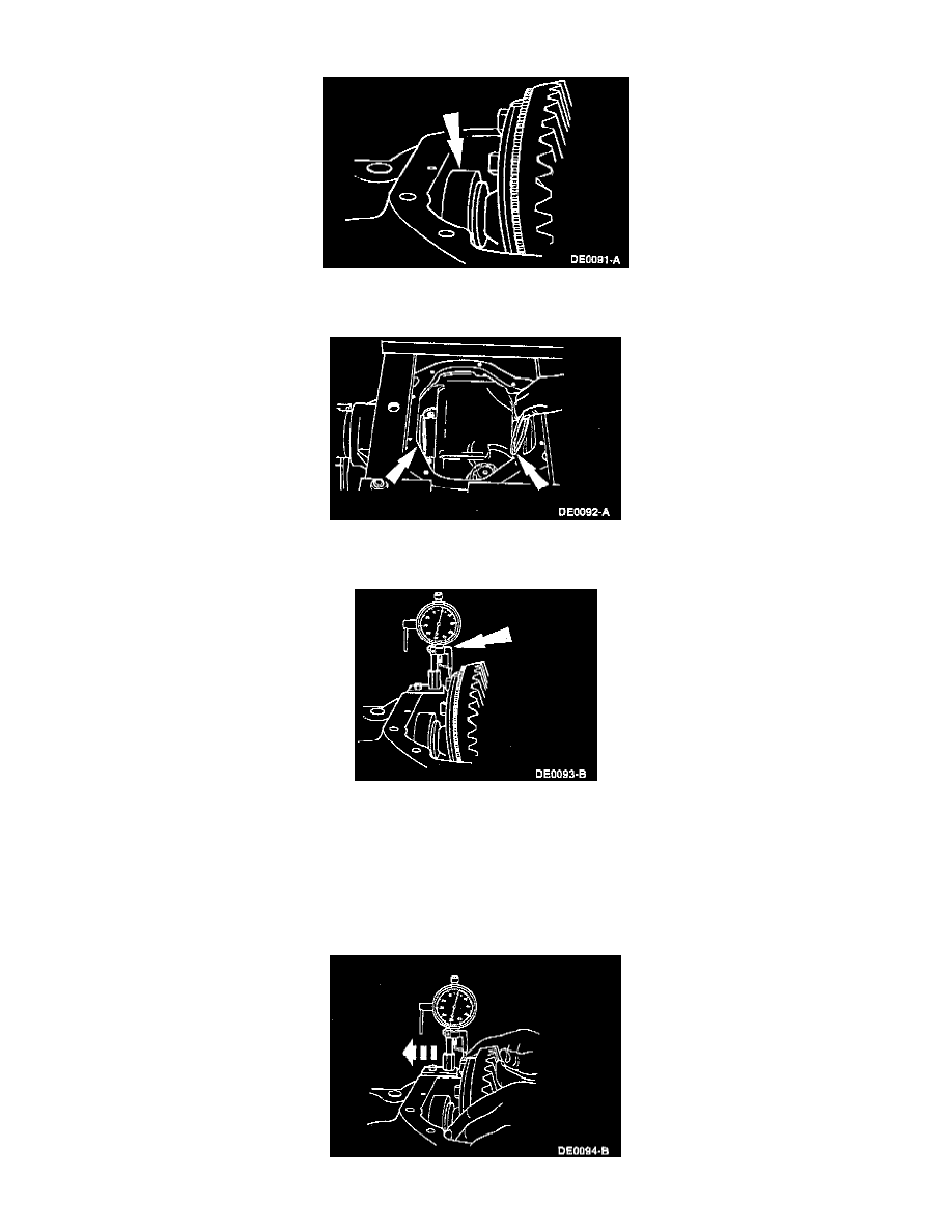
4. Mount the Dial Indicator/Magnetic Base or Dial Indicator with Bracketry as shown. Locate the tip of the indicator with the Clutch Housing
Alignment Adapter on a flat surface of one of the ring gear screw spot faces.
NOTE:
-
The Dial Indicator should have a minimum travel capability of 5.08 mm (0.200 inch).
-
The rear axles use a combination of hard inboard spacers and selective outboard shims. The old outboard selective shims can be used as a
starting point. If additional shimming is required other than what can be obtained with the hardened inboard spacers, a new outboard
selective shim must be used.
5. Force the differential case as far as possible toward the indicator. With force still applied, set indicator at 0.