
E 350 Van L6-300 4.9L VIN E 1-bbl (1982)
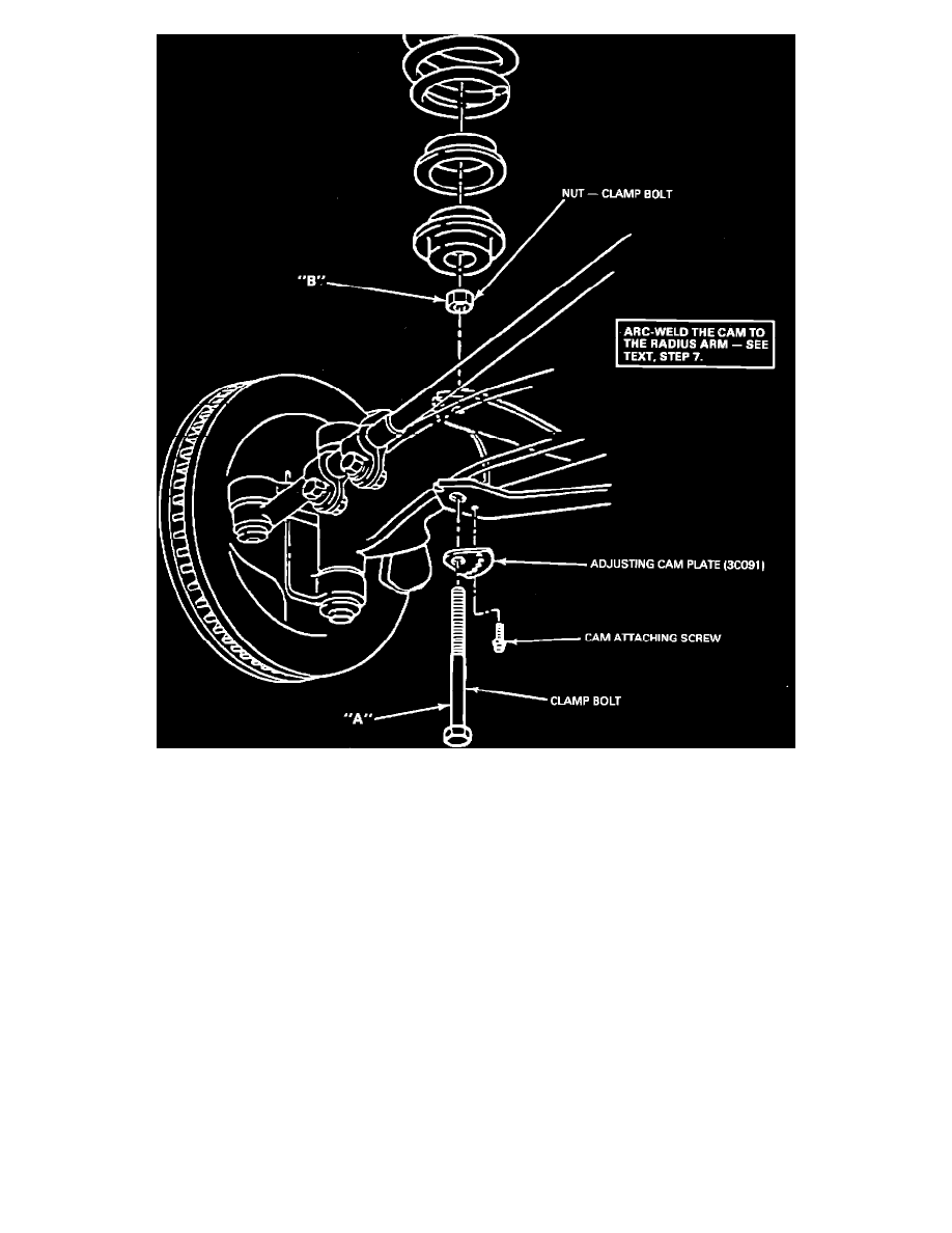
Figure 11 - TYPICAL INSTALLATION - FRONT AND RADIUS ARM
6.
Figure 11 shows a typical vehicle installation. TORQUE BOLT "A" AND NUT "B" TO 270-330 FT. LBS. When increasing caster 2 degrees or
more, the ears of the radius arm should be bent upward slightly to help install and seat the axles. Do not use heat to bend.
7.
Reset front wheel toe after installation is complete. AFTER THE DESIRED ALIGNMENT IS ASSURED THE CAM MUST BE WELDED TO
THE ARM ARC WELD ONE INCH MINIMUM LENGTH ALONG TWO SIDES OF THE CAM.
NOTE:
The metal adjusting cam plate has a Ford logo stamped on it to identify it for E100- 150 and F250-350 4x2 vehicles only on vehicles with a
front stabilizer bar. The bar mounting bracket may be reworked to provide clearance for the self-tapping screw. Do not use parts from kit
E4TZ- 3K064-A on these vehicles.
PART NUMBER
PART NAME
CLASS
E5TZ-3K064-A
Kit Caster Adjustment
C
OTHER APPLICABLE ARTICLES: 85-13-12
WARRANTY STATUS: Reimbursable within the provisions of the Warranty and Policy Manual.
OPERATION: SP3360B85L
TIME:
Left - F Series: 2.4 Hrs.
Econoline:
2.8 Hrs.
OPERATION: SP3360B85R
TIME:
Right - F Series: 2.4 Hrs.
Econoline:
2.8 Hrs.
OPERATION: SP3360B85T
TIME:
Both - F Series: 3.8 Hrs.