
E 350 Van L6-300 4.9L VIN E 1-bbl (1982)
Front Steering Knuckle: Service and Repair
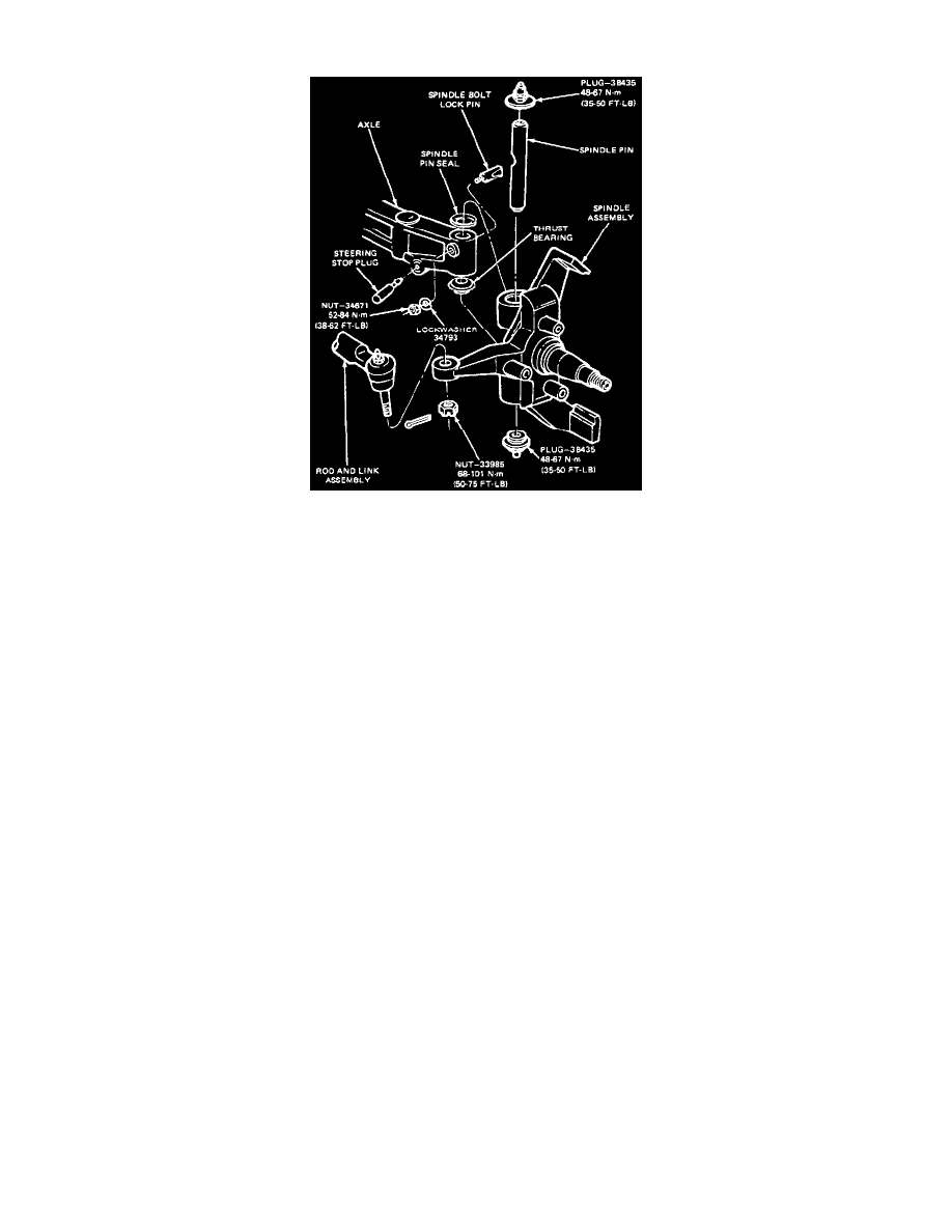
Spindle
REMOVE
1. Raise the front of the vehicle and install safety stands.
2. Remove the wheel and tire assembly.
3. Remove the caliper assembly from the rotor and hold it out of the way with wire.
4. Remove the dust cap, cotter pin, nut retainer, nut, washer, and outer bearing, and remove the rotor from the spindle.
5. Remove inner bearing cone and seal. Discard the seal.
6. Remove brake dust shield.
7. Disconnect the steering linkage from the spindle arm by removing the cotter pin and nut, and then removing the tie rod end from the spindle arm
with tie Rod End Remover, TOOL-3290-D or equivalent.
8. Remove the nut and lockwasher from the lock pin, and remove the lock pin.
9. Remove the upper and lower spindle pin plugs; then, drive the spindle pin out from the top of the axle and remove the spindle and thrust bearing.
Remove the spindle pin seal and thrust bearing.
INSTALL
1. Make sure the spindle pin hole in the axle is free of nicks, burrs, corrosion or foreign material. Clean up the bore as necessary and lightly coat the
surface with a lithium-base grease, Long-Life Lubricant, C1AZ-19590-BA (ESA-M1C75-B) or equivalent.
2. Install a new spindle pin seal with the metal backing facing up towards the bushing into the spindle. Gently press seal into position, being careful
not to distort the casing.
3. Install a new thrust bearing with the lip flange facing down towards the lower bushing. Press until the bearing is firmly seated against the surface
of the spindle.
4. Lightly coat the bushing surfaces with grease and place the spindle in position on the axle.
5. Hold the spindle with thrust bearing in place tight against the axle and measure the space between the axle and the spindle at the top of the axle. If
the vehicle uses shims, select the proper shims and install.
6. Install the spindle pin with the "T" stamped on one end towards the top, and the notch in the pin aligned with the lock pin hole in the axle. Insert
the spindle pin through the bushings and axle from the top until the spindle pin notch and axle lock pin hole are in line.
7. Install the lock pin with the threads pointing forward and the wedge groove facing the spindle pin notch. Firmly drive the lock pin into position
and mount the lockwasher and nut. Tighten the nut to 52-84 Nm (38-62 ft lb).
8. Install the spindle pin plugs into the threads at the top and bottom of the spindle. Tighten the plugs to 48-67 Nm (35-50 ft lb).
9. Lubricate the spindle pin and bushings with Long-Life Lubricant C1AZ-19590-BA (ESA-M1C75-B) or equivalent, through both fittings until
grease is visible seeping past the upper seal at the top and from the thrust bearing slip joint at the bottom. If grease does not appear, recheck the
installation procedure to correct the problem. Lack of adequate lubrication will result in rapid failure of the spindle components.
10. Install the dust shield.
11. Pack the inner and outer bearing cone with bearing grease. Use a bearing packer. If a bearing packer is unavailable, pack the bearing cone by hand
working the grease through the cage behind the rollers.
12. Install the inner bearing cone and seal. Install the hub and rotor on the spindle.
13. Install the outer bearing cone, washer, and nut. Adjust bearing end play and install the nut retainer, cotter pin and dust cap.
14. Install the caliper.