
E 350 Van V8-7.3L DSL (1988)
6. With a light hammer tap the steering shaft out the bottom of the steering column.
7. Clip the ignition switch in LOCK position and remove ignition switch and actuation rod.
8. Remove the automatic transmission hood and lens assembly, (if so equipped).
9. Loosen the upper flange retaining nuts until 1 or 2 threads remain engaged, pinch the nuts toward each other, and pull flange off outer tube.
10. Remove shift tube retaining bolt from the bottom of the shift socket.
11. Remove the shift/socket flange extension.
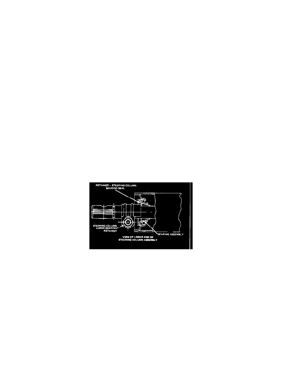
12. Remove the lower bearing retainer, if so equipped.
13. Withdraw shift tube from top or bottom of the steering column.
14. Withdraw lower shift arms and spacer from column outer tube.
15. Remove lamp from flange and separate turn signal-hazard warning switch from flange.
16. Remove upper shaft bearing and insulator cover from upper flange by tapping with light hammer from opposite side of flange.
17. Disassemble the upper flange and locking mechanism.
18. Remove the floor opening cover plate from the outer tube.
Assembly
1. Place bushing in socket retainer in outer tube.
2. Place bushing on upper hub and wave washer on lower hub of shift socket.
3. Insert lower shift arms and spacer in outer tube.
4. Insert shift tube assembly from top or bottom of column.
5. Install shift socket onto shift tube in outer tube or flange extension onto outer tube 1.7-2.3 Nm (15-20 in-lbs).
6. Install shift tube retaining screw in the bottom of the shift socket.
7. Place turn signal-hazard warning switch wiring harness through flange.
8. Press lamp and wire into flange.
9. Feed turnsignal harness through shift socket Pinching the flange casting subassembly retaining nuts toward each other, install flange.
10. Install ignition switch actuation rod, ignition switch and hand start the washer-nuts retaining the switch.
11. Adjust the ignition switch.
12. Install the steering shaft from the column bottom.
13. Install the lower bearing retainer.
14. Install the upper shaft bearing and insulator cover.
15. Install the snap ring on the shaft above the upper bearing.
16. Loosen the lower bearing retainer so it is free to slide on the steering shaft.
17. Seat the upper bearing by tapping on the upper end of the shaft with a rubber mallet.
18. Preload the lower bearing by sliding the bearing retainer against the bearing with the thumb and fore finger while holding the steering shaft.
Tighten the retainer nut to 14-18 Nm (10-14 ft-lb) while holding the bearing retainer.
19. Install the turnsignal-hazard warning switch and tighten the 3 retaining screws.
20. Install the automatic transmission hood and lens, if so equipped.
21. Install the hand shift lever and pivot pin.
22. Install the turn signal lever.
23.Install the steering column.
Steering Column Flange and Locking Mechanism Subassembly
1. Install lock actuator insert in rear of flange and tighten screw 1.7-2.8 Nm (15-25 in-lbs).
2. Insert lock actuator assembly through opening in front of flange until it bottoms against insert.
3. Install lock drive gear through lock cylinder opening such that the last gear tooth aligns with the last tooth on the actuator assembly when the
actuator is fully rearward.
4. Install the lock bearing.
5. Install the snap ring.
6. with the lock cylinder in the "run" and the retaining pin depressed. Insert the lock cylinder into the flange.
7. Attach PRND21 insert to front of flange.
8. Position spring on lock release lever assembly and position lever assembly through hole in front of flange torque spring until lever assembly is
allowed to drop into place.