
E 350 Van V8-7.3L DSL Turbo VIN F (1995)
6.
Remove two screws retaining ignition control module to heat-sink and remove ignition control module.
7.
Coat metal baseplate of the replacement ignition control module uniformly with silicone compound, approximately .0179 mm (1/31-inch) thick.
Use Silicone Dielectric Compound WA-10 D7AZ-19A331-A (ESE-M1C171-A) or equivalent.
8.
Position ignition control module onto heat-sink and tighten two retaining screws to 1.7-4.0 N-m (15-35 in-lb).
9.
Install ignition control module heat-sink assembly useing two retaining screws, and tighten to 9-14 N-m (80-124 in-lb).
10.
Connect engine control sensor wiring to the ignition control module.
11.
On Econoline models only, reposition and connect battery. Start engine, verify operation.
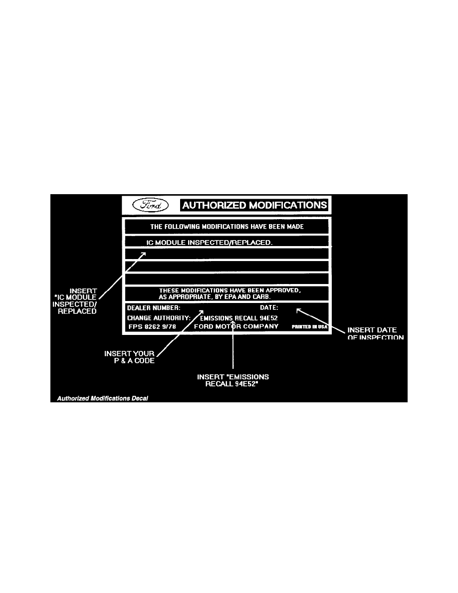
Authorized Modifications Labels And California "Emissions Recall-Proof of Corrections" Certificates
^
Obtain, prepare and attach an Authorized Modifications Label (available at no-charge {package of 25 with overlay} as part number FCS-8262 or
DOES II). Write on the label "IC Module Inspected/Replaced", authority, Emissions Recall 94E52", your P&A Code and date of repair as shown
below.
^
Provide California owners with "Emissions Recall-Proof of Correction " Certificates.
Authorized Modifications Decal
Dealer Letter
RECALL NUMBER
94E52
Date: Feb., 1995
PARTS
AVAILABILITY
At Dealers By: as Req'd
0% of Parts Direct
Shipped to Dealers
At PDC By: Now
Date in Owner Letter: March, 1995
To:
All Dealers