
Starter Motor Testing and Inspection for E-350 Van - VIN F (1995)
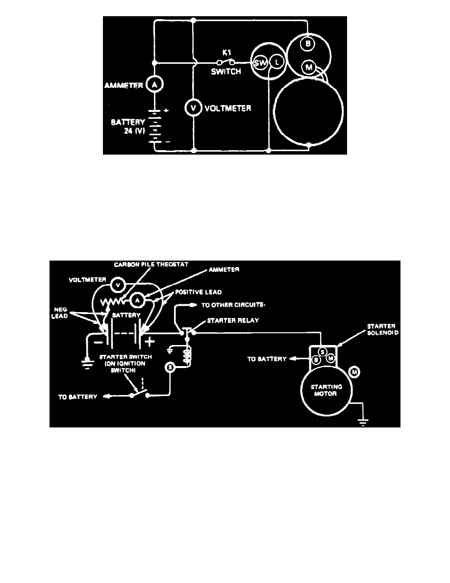
Starter No-load Test Connections
1. Connect starter as shown.
2. Close switch K1 and check starter operation. Starter should operate smoothly.
3. If starter rotates slowly, check clearance between the armature and starter housing. Clearance should be 0.001-0.020 inch. Clearance is determined
by the shim behind the bearing in the end cover.
Field Grounded Circuit Test
1. Check insulation between yoke and field terminal using circuit tester. Circuit tester should show infinite resistance.
2. Ensure there is continuity between lead wires.
Starter Load Test
Starter Load Test Connections
1. Connect test equipment as shown, ensuring that there is no current flowing through ammeter and heavy duty carbon pile rheostat portion of circuit.
2. Disconnect push on connectors at starter solenoid and connect remote control starter switch from positive battery cable to S terminal of starter
solenoid.
3. Crank engine with remote starter switch and determine exact reading on voltmeter.
4. Stop cranking engine, then reduce resistance of carbon pile until voltmeter indicates same reading as when engine was cranked. Ammeter should
read less than 500 amps.