
E 350 Van V8-7.3L DSL Turbo VIN F (1995)
NOTE: Do not remove any cup plugs.
5. Remove main regulator valve internal snap ring, then the valve assembly.
6. Remove converter regulator valve retaining clip, then the valve assembly.
7. Remove converter clutch shift valve retaining clip, then the valve assembly.
8. Remove gerotor gear set from pump body.
ASSEMBLE
1. Install main regulator valve assembly, converter regulator valve assembly, and converter clutch shift valve assembly as shown in the Exploded
View Of Front Pump image.
2. Lubricate and install gerotor gears into pump housing.
NOTE: Dot on inner gerotor gear must face the control body assembly.
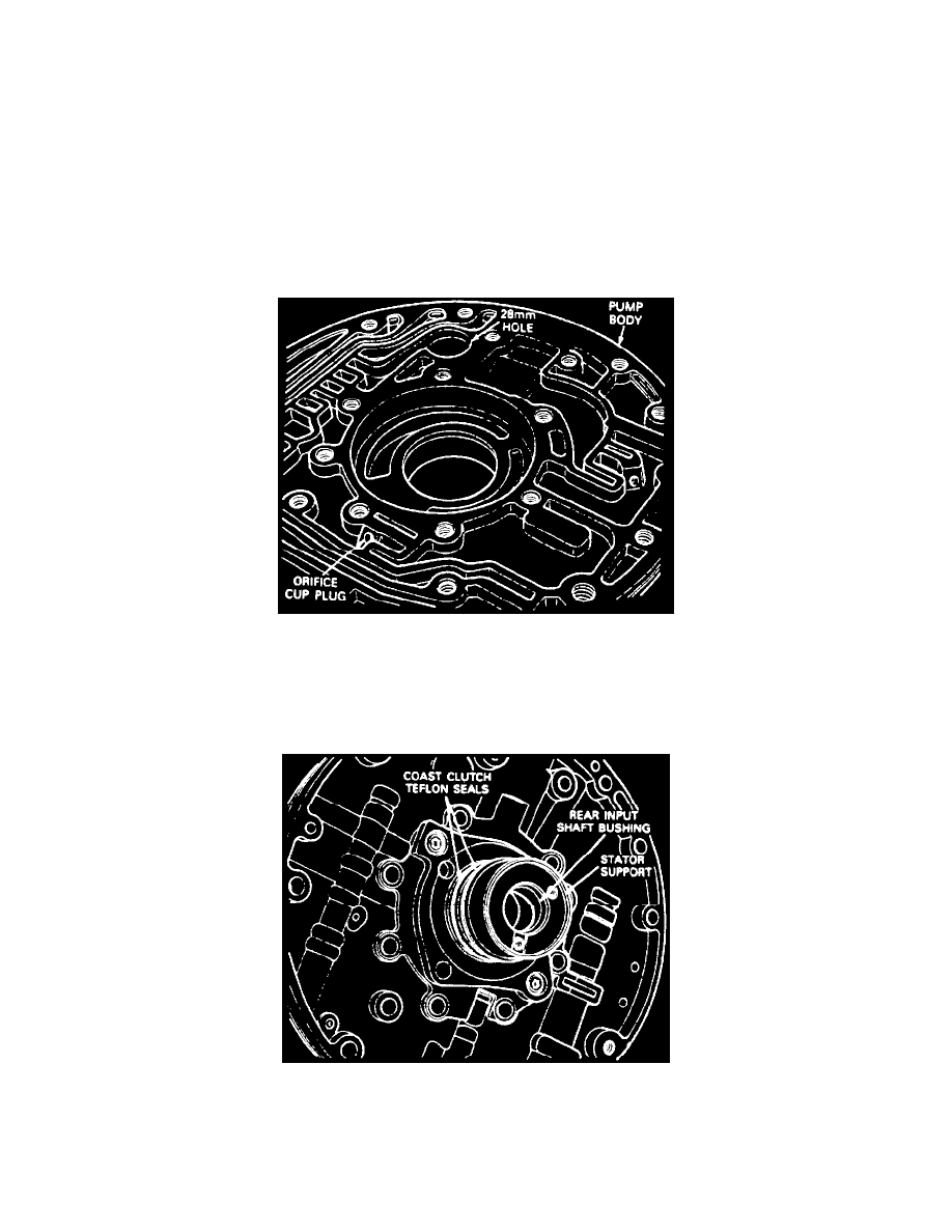
28 MM Hole Location
3. Lower control body and stator assembly onto pump body. Align 28 mm round hole in control body with 28 mm hole in pump body.
4. Loosely install eleven retaining bolts into pump body.
5. Install banding tool No. D89L-77000-A or equivalent with clamp by filter inlet.
6. Align outer bolt holes and tighten banding tool. This aligns input shaft bushings to the converter hub bushings.
Installing Coast Clutch Seals
7. Install coast clutch Teflon seals, then the converter lock-up seal on front of stator support.
8. Lubricate and install pump outer diameter seal. Ensure groove is clean and free of burrs.