
E 350 Van V8-7.3L DSL Turbo VIN F (1995)
10. Hold differential pinion gears in place and insert pawl of rotating tool between two side gear teeth, then pull on handle so that top side gear rotates
and allows differential pinion gears to rotate and enter into case.
NOTE: It may be necessary to slightly tighten or loosen forcing screw to permit gear movement.
11. Put on tool until handle hits case, then remove pawl from between gear teeth and position handle and pawl. Repeat this step until holes of
differential pinion gears are perfectly aligned with holes of case.
12. Lubricate both sides of pinion spherical washers with suitable lubricant.
13. Tighten forcing screw to obtain installation clearance for spherical washers.
14. Install spherical washers, ensure holes of washers and gears are perfectly aligned with holes of case, then remove forcing screw, rotating tool, and
step plate.
15. Install pinion shaft in differential case, then the cross shaft locking pin.
Dana/Spicer Model 70-1HD, 70-2U
DISASSEMBLE
1. Scribe a mark between the differential case halves to be used during assembly. Also, mark the pinion mate shafts and corresponding ramps for
assembly in original locations.
2. Clamp differential assembly in a soft jaw vise.
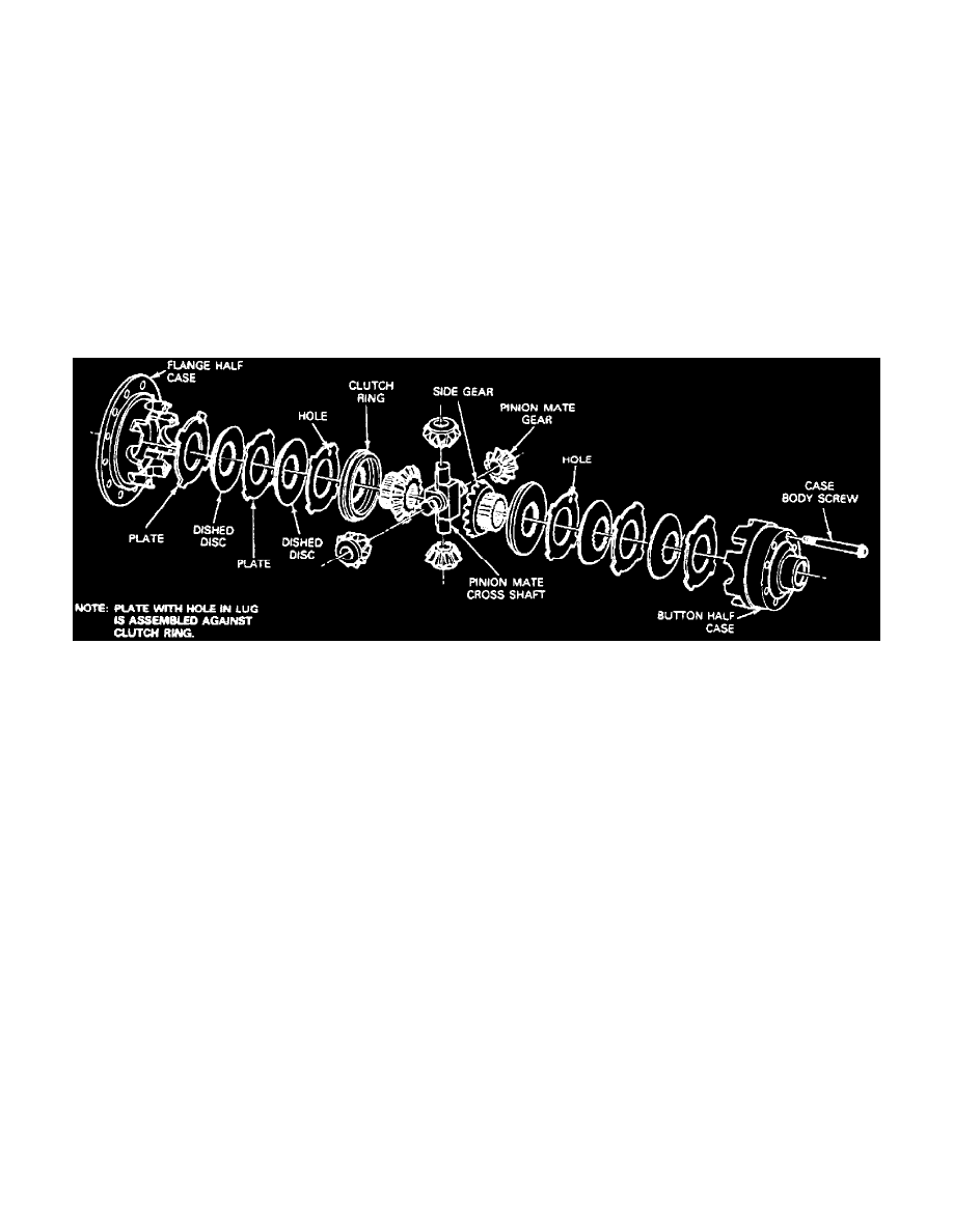
Fig. 6 Exploded View Of Powr-Lok Locking Differential.
3. Loosen but do not remove the case half retaining bolts.
4. Place assembly on bench with the ring gear half down and remove case half retaining screws.
5. Remove the cover half of the case.
6. Remove upper mate shaft, side gear, side gear ring and clutch pack. Retain parts with cover half of case so they can be installed in original
position.
7. Remove lower mate shaft, side gear, side gear ring and clutch pack from drive gear case half.
ASSEMBLE
1. Place side gear ring from ring gear half of case on a pinion flange or other suitable fixture so the case is approximately four inches above bench.
2. Lubricate clutch plates and assemble clutch pack on side gear ring.
3. Place ring gear side of case over clutch pack and side gear ring. Ensure the clutch plate lugs enter the slots in the case and that the case bottoms on
the clutch pack.
4. Invert the assembly. Hold assembly together while inverting.
5. Install the ring gear case half side gear in side gear ring.
6. Install axle shaft spacer in cross shaft.
7. Install the ring gear case half pinion mate shaft and pinions on the side gear ring.
8. Install the cover half pinion mate shaft and pinions.
9. Place side gear on pinions, then the side gear ring on side gear.
10. Assemble clutch pack on side gear ring, aligning clutch pack lugs.
11. Install cover half of case over assembly, aligning the marks made during disassembly.
12. Install the case half retaining bolts, turning the bolts to engage a few threads only.
13. Insert axle shaft into assembly and align the splines of the side gears and side gear rings. With the axle shafts in position, tighten case half retaining
bolts to specifications.
14. Remove axle shafts.
15. If the differential has been assembled properly, each pinion mate cross shaft should be tight on its ramp. However, if clearance is present, it should
not exceed 0.010 inch and be equal at all four cross shaft ends.