
E 350 Van V8-7.3L DSL Turbo VIN F (1995)
Differential Case: Testing and Inspection
1. Apply a suitable multi-purpose long-life lubricant to side gear thrust washers, hub, thrust face of side gears, pinion mate gears and spherical
washers.
2. Hold side gears in place in case, then install pinion mate gears and spherical washers.
3. Rotate side gears until holes in washers and pinion mate gears align with holes in case.
NOTE: If gears cannot be rotated by hand, install an axle shaft into side gear spline and use a pipe wrench to turn shaft.
4. Use a drift to align holes, then insert pinion mate shaft and drive into case to remove drift, ensuring lockpin hole in shaft aligns with lockpin holes
in case.
5. Insert lockpin, then peen some metal of case over pin to lock it into place. The semi-float shaft riding bearing design uses a lockpin that is installed
using a 12 point socket. Use a new lockpin and assemble finger tight. This prevents differential side gears and differential pinion mate gears from
rotating inside case and dropping out when servicing the carrier section.
NOTE: A new lockpin should be installed after assembling the axle shafts.
6. If applicable, install exciter ring as follows:
a. Align tab in exciter ring with slot in differential case, then thread two ring gear bolts through case into ring gear to ensure bolt hole alignment.
Tab on exciter ring must be aligned with slot in differential case.
b. Press exciter ring and ring gear onto differential case. Ring gear acts as a pilot for exciter ring.
c. Apply threadlock and sealer part No. E0AZ-19554-AA, or equivalent, to new ring gear bolts.
7. Attach ring gear to differential case using new bolts, then tighten bolts alternately and evenly.
8. Clean trunnions on differential and install bearings onto differential case. Remove all burrs and nicks from hubs so bearings rotate freely.
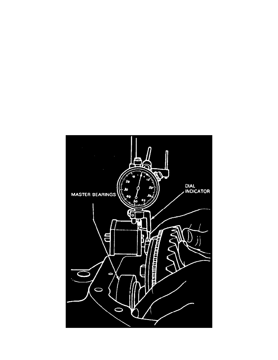
Fig. 10 Total Differential Case Endplay Inspection
9. Place differential case into carrier (without pinion). Differential case should move freely in carrier assembly. Position a suitable dial indicator