
Econoline E350 1 Ton V8-5.4L CNG VIN M (1999)
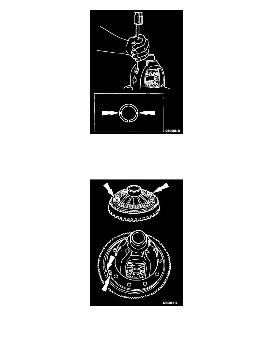
6. Assemble the differential pinion shaft lock pin. Peen the metal of the differential case over the differential pinion shaft lock pin in two places, 180
degrees apart, to lock in place. Note the location of the slot in the differential pinion shaft lock pin and peen 90 degrees away.
7. NOTE: The tab on the anti-lock speed sensor ring must be aligned with the slot in the differential case.
NOTE: Apply Thread lock and Sealer EOAZ-19554-AA or equivalent meeting Ford specification WSK-M2G315-A5 (TYPE II) to the new ring
gear bolts.
Align the tab in the anti-lock speed sensor ring with the slot in the differential case. Start the two ring gear bolts through the differential case flange
into the ring gear to make sure the differential case and the ring gear bolt hole align.