
Econoline E350 1 Ton V8-5.4L CNG VIN M (1999)
6. Force the differential as far as it will go in the opposite direction.
7. After making sure the readings are correct, remove the indicator and the differential from the rear axle housing. Do not remove the master bearings
from the differential case at this time.
8. This reading is the total differential case end play, which will be needed for assembly of the differential into the housing.
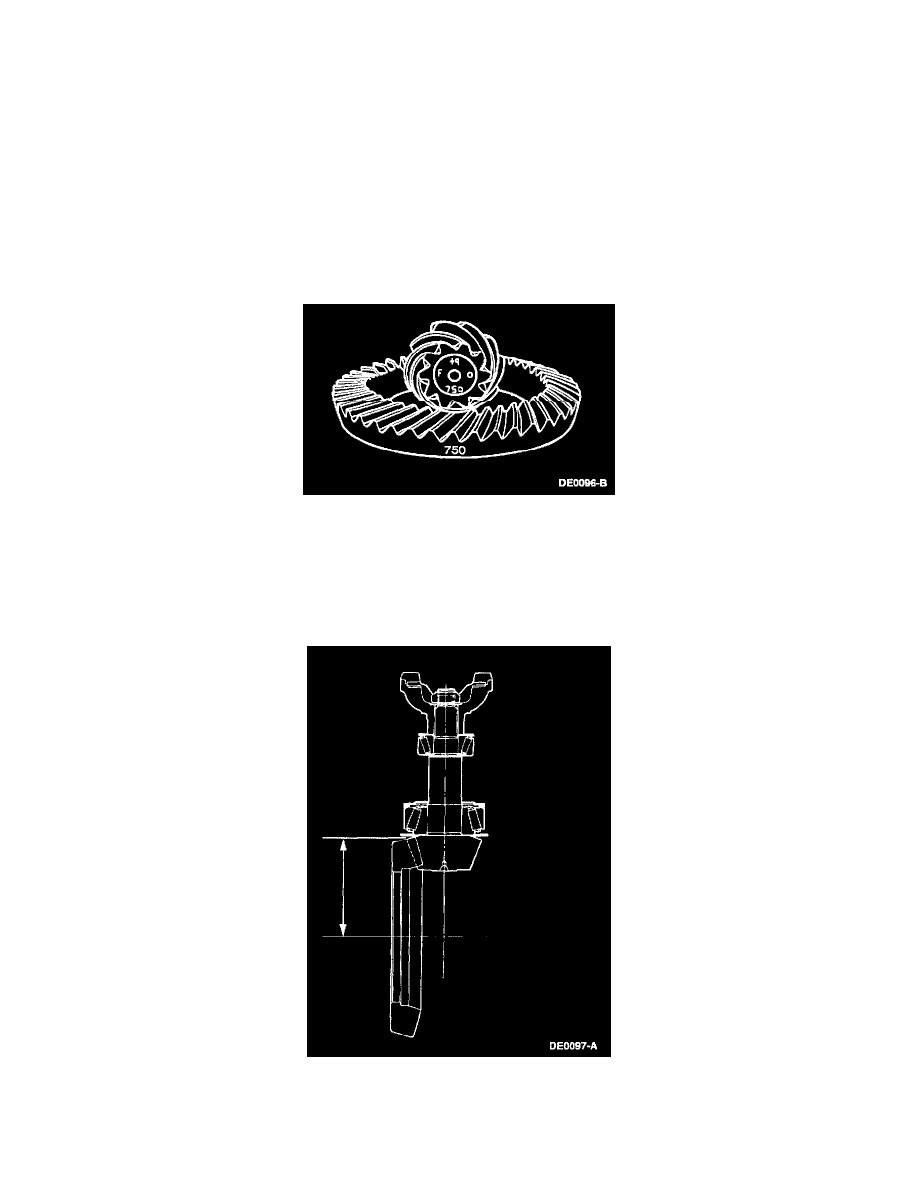
Pinion Ring Gear Variation Number
NOTE: If the rear axle drive pinion shaft oil slinger is bent or mutilated, it must be installed new.
NOTE: Ring gear and pinions are supplied in matched sets only. Matching numbers are etched on both the ring gear and pinion for verification. If a
new ring gear and pinion is being used, verify the numbers of each ring gear and pinion before proceeding with assembly. The end of the pinion with
the etched figures shown is known as the "button" end.
NOTE: Use the gear contact pattern method to make sure the final pinion position is valid.
1. Shim the drive pinion as follows:
^
On the button end of each pinion, there is etched a plus (+), a minus (-) or a zero (0) number, which indicates the best running position for each
particular ring gear. This dimension is controlled by the shimming behind the inner pinion bearing cup (the backface).
^
For example, if a pinion is etched m+8 (+3), this pinion requires 0.08 mm (0.003 inch) less drive pinion shims than a pinion etched "0". This
means by removing drive pinion shims, the mounting distance of the pinion is increased, which is what an m+8 (+3) indicates. Or if a pinion is
etched m-8 (-3), add 0.08 mm (0.003 inch) more shims than would be required if the pinion were etched "0". By adding 0.08 mm (0.003 inch)
pinion shims, the mounting distance of the pinion is decreased, which is what an m-8 (-3) indicates.
2. Measure the distance between the centerline of the ring gear to the backface of the drive pinion.
^
The distance from the centerline of the ring gear to the backface of the pinion:
-
127 mm (5.000 inches) for Model 60-lU
-
136.5 mm (5.375 inches) for Model 70