
Econoline E350 1 Ton V8-5.4L SOHC VIN L (1999)
3. Install the outboard differential selective spacers into the rear axle differential carrier. Assemble the differential case into the rear axle differential
carrier (less pinion).
4. NOTE: The Dial Indicator should have a minimum travel capability of 5.08 mm (0.200 inch).
NOTE: The rear axles use a combination of hard inboard spacers and selective outboard shims. The old outboard selective shims can be used as a
starting point. If additional shimming is required other than what can be obtained with the hardened inboard spacers, a new outboard selective
shim must be used.
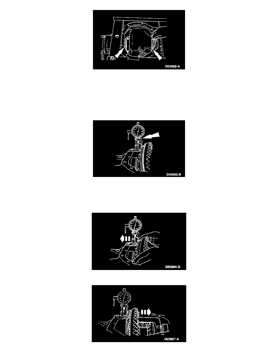
Mount the Dial Indicator/Magnetic Base or Dial Indicator with Bracketry as shown. Locate the tip of the indicator with the Clutch Housing
Alignment Adapter on a flat surface of one of the ring gear screw spot faces.
5. NOTE: Repeat Steps 5-7 until you have obtained the same reading each time. Record the reading of the indicator. This is the total amount of
differential bearing shims required (less preload) and will be calculated later during assembly.
Force the differential case as far as possible toward the indicator. With force still applied, set indicator at 0.