
Econoline E550 V8-7.3L DSL Turbo VIN F (2002)
16. Remove the clockspring.
-
Feed the wiring harness through the instrument panel (04320).
Installation
Vehicles receiving a new clockspring
1. NOTE: A new clockspring is supplied in a centralized position and held there with a key.
Remove the key from the clockspring, holding the rotor in its centralized position.
-
Do not allow the clockspring rotor to turn.
Vehicles needing clockspring recentering
2. WARNING: Incorrect centralization may result in premature component failure. If in doubt when centralizing the clockspring, repeat
the centralizing procedure. Failure to follow this instruction may result in personal injury.
CAUTION: Make sure the road wheels are in the straight ahead position.
NOTE: If a clockspring has rotated out of center, follow through with this step.
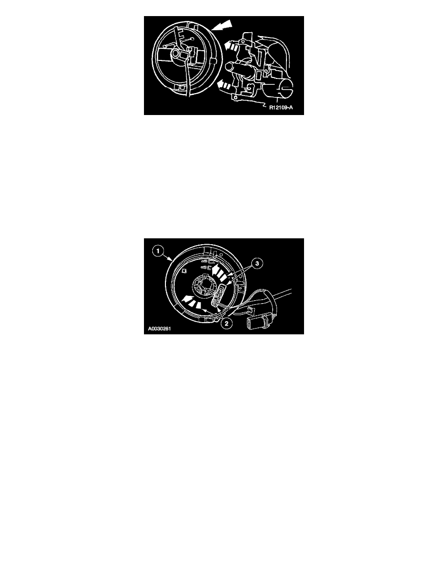
Centralize the clockspring.
1
Hold the clockspring outer housing stationary.
2
CAUTION: Overturning will destroy the clockspring. The internal ribbon wire acts as the stop and can be broken from its internal
connection.
While turning the rotor clockwise, carefully feel for the ribbon wire to run out of length and for a slight resistance. Stop turning at this point.
3
Turn the clockspring counterclockwise approximately 2.25 turns. This is the center point of the clockspring.
-
Do not allow the rotor to turn from this position.
Vehicle repairs reusing the same clockspring
3. NOTE: When the tape is removed, do not allow the clockspring to turn.
Remove the tape applied during clockspring removal.
All vehicles