
Edge AWD V6-3.5L (2009)
ground; or between the trailer tow RH stop/turn relay pin 2, circuit CLS19 (VT/OG), BJB face side and ground.
-
Is the voltage greater than 10 volts?
Yes
GO to Z4.
No
REPAIR circuit CLS18 (GY/BN) (LH stop/turn) or circuit CLS19 (VT/OG) (RH stop/turn) for an open. TEST the system for normal operation.
-------------------------------------------------
Z4 CHECK THE BJB
-
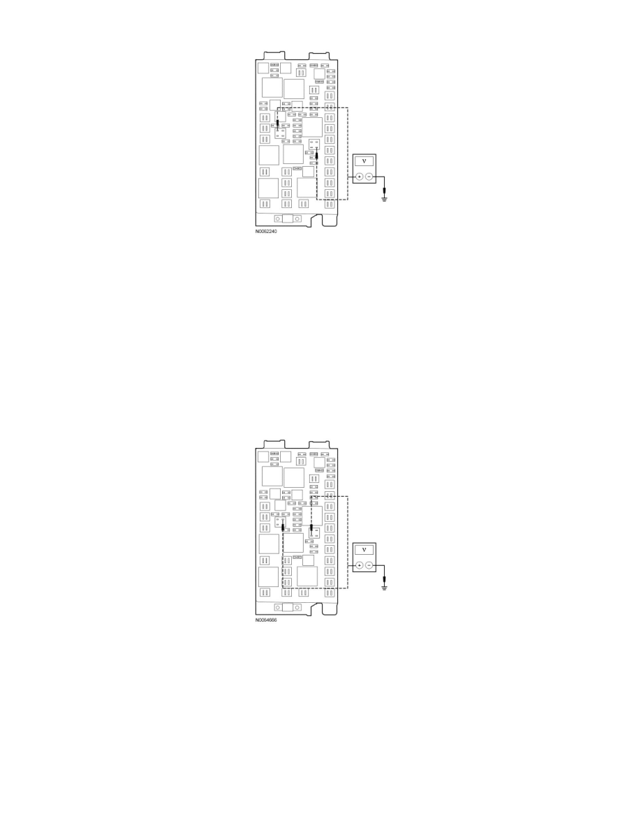
Measure the voltage between the trailer tow LH stop/turn relay pin 3, BJB face side and ground; or between the trailer tow RH stop/turn relay pin
5, BJB face side and ground.
-
Is the voltage greater than 10 volts?
Yes
GO to Z5.
No
INSTALL a new BJB. TEST the system for normal operation.
-------------------------------------------------
Z5 CHECK FOR VOLTAGE TO THE STOP/TURN LAMP RELAY USING THE RELAY GROUND PIN
-
Measure the voltage between the trailer tow LH stop/turn relay pin 3, BJB face side and the trailer tow LH stop/turn relay pin 2, circuit GD120