
Edge AWD V6-3.5L (2009)
5. Install the driver side D-pillar trim panel.
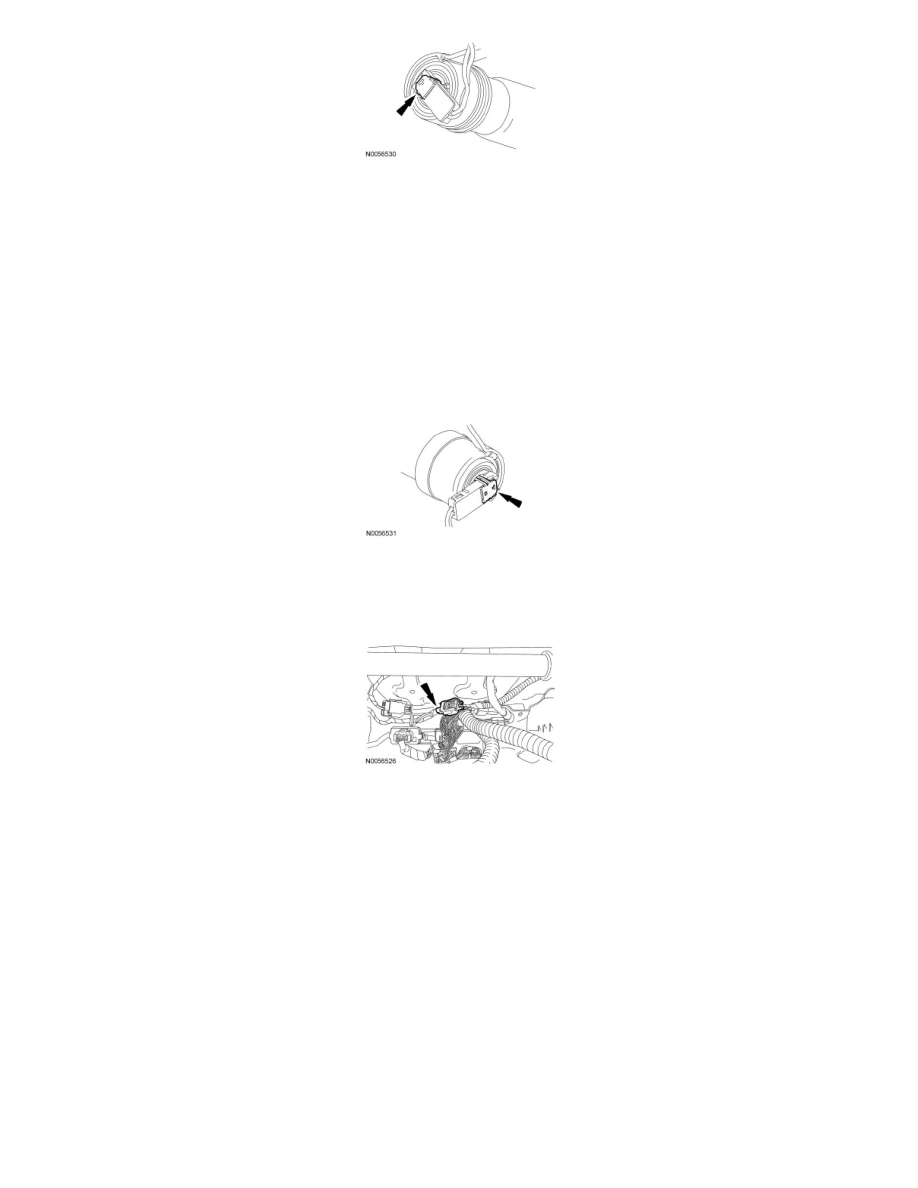
6. NOTICE: Do not install the safety canopy module electrical connector by the locking button. Damage to the locking button may occur.
NOTICE: The safety canopy module electrical connector locking button must be in the released position when the connector is being
installed or connector damage may occur.
NOTICE: The safety canopy module electrical connector is unique and cannot be reversed when connected to the safety canopy module.
Match the electrical connector key to the keyway in the safety canopy module. Do not force the electrical connector into the safety canopy
module. Damage to the connector or component may occur.
With the locking button released, install the passenger safety canopy module electrical connector fully into the passenger safety canopy module
and seat the locking button.
7. Install the passenger side D-pillar trim panel.
8. Connect the passenger seat side air bag module electrical connector and then slide and engage the seat side air bag electrical connector locking
clip.
MKX
9. NOTICE: Do not install the passenger air bag module electrical connectors by the locking buttons. Damage to the locking buttons may
occur.
NOTICE: The passenger air bag module electrical connector locking buttons must be in the released position when the connector is being
installed or connector damage may occur.
NOTICE: The passenger air bag module electrical connectors are unique and cannot be reversed when connected to the passenger air
bag module. Match the electrical connector key to the keyway in the passenger air bag module. Do not force the electrical connectors into
the passenger air bag module. Damage to the connector or component may occur.
NOTE: RH side shown, LH similar.
Position the passenger air bag module on the cross vehicle beam. With the locking buttons released, install the 2 passenger air bag module
electrical connectors fully into the passenger air bag module and seat the locking buttons.