
Edge AWD V6-3.5L (2009)
32. From under the rear of the driver seat, detach the driver seat side air bag module electrical connector from the seat cushion frame. Then slide and
disengage the driver seat side air bag module electrical connector locking clip, and then release the tab and disconnect the driver seat side air bag
module electrical connector.
33. Install RCM fuse 46 (7.5A) to the SJB.
34. Connect the battery ground cable.
Reactivation
All vehicles
1. Remove RCM fuse 46 (7.5A) from the SJB.
2. Disconnect the battery ground cable and wait at least one minute.
3. Connect the driver seat side air bag module electrical connector and then slide and engage the seat side air bag electrical connector locking clip.
Then attach the driver seat side air bag module electrical connector to the seat cushion frame.
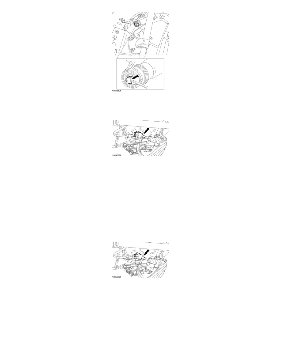
4. NOTICE: Do not install the safety canopy module electrical connector by the locking button. Damage to the locking button may occur.
NOTICE: The safety canopy module electrical connector locking button must be in the released position when the connector is being
installed or connector damage may occur.
NOTICE: The safety canopy module electrical connector is unique and cannot be reversed when connected to the safety canopy module.
Match the electrical connector key to the keyway in the safety canopy module. Do not force the electrical connector into the safety canopy
module. Damage to the connector or component may occur.
With the locking button released, install the driver safety canopy module electrical connector fully into the driver safety canopy module and seat
the locking button.