
Edge AWD V6-3.5L (2009)
GO to A3.
No
REFER to Computers and Control Systems Information, Pinpoint Tests, pinpoint test QA to diagnose no communication with the PCM.
-------------------------------------------------
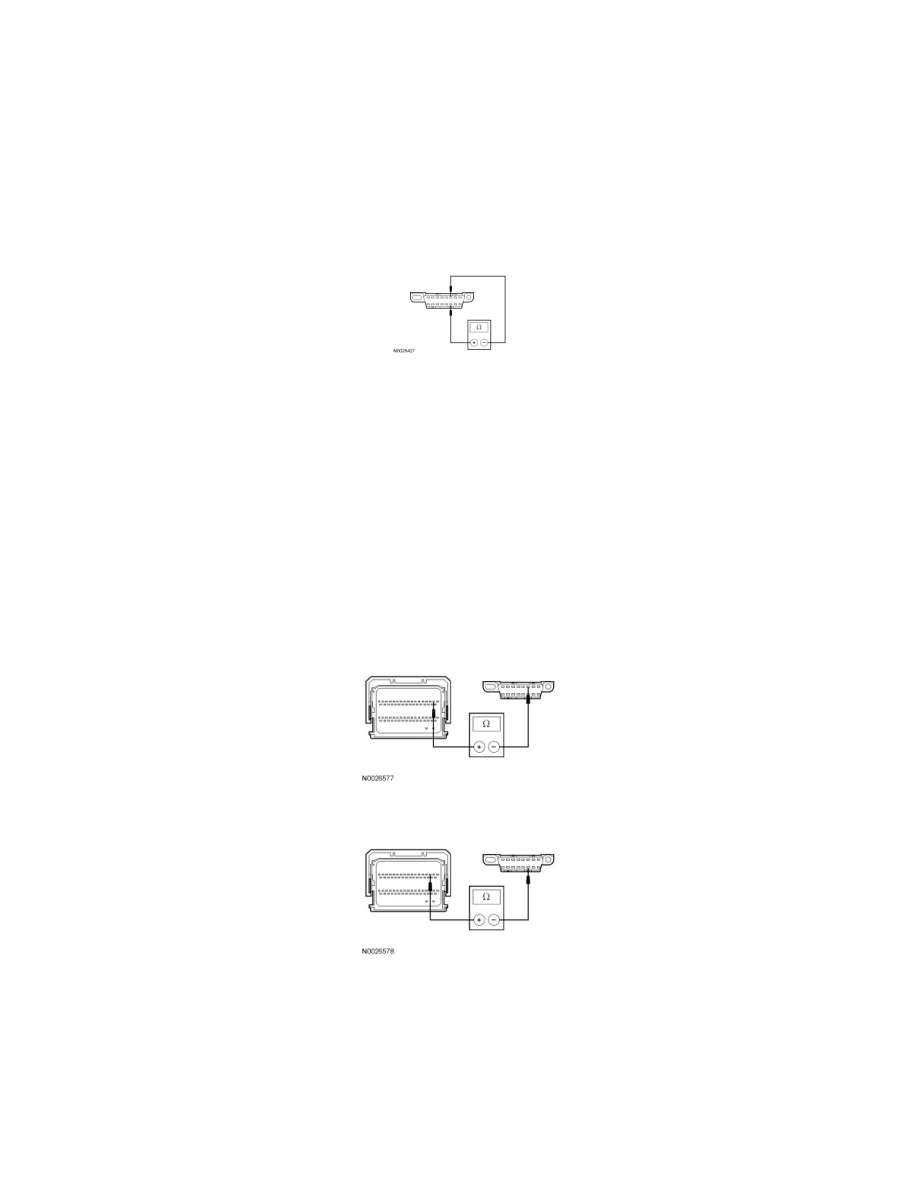
A3 CHECK THE HS-CAN TERMINATION RESISTANCE
-
Ignition OFF.
-
Disconnect: Negative Battery Cable.
-
Measure the resistance between the Data Link Connector (DLC) C251-6, circuit VDB04 (WH/BU), harness side and the DLC C251-14, circuit
VDB05 (WH), harness side.
-
Is the resistance between 54 and 66 ohms?
Yes
CONNECT the negative battery cable. GO to A5.
No
GO to A4.
-------------------------------------------------
A4 CHECK THE HS-CAN CIRCUITS BETWEEN THE PCM AND THE DLC FOR AN OPEN
-
Disconnect: PCM C175b.
-
Measure the resistance between the PCM C175b-2, circuit VDB04 (WH/BU), harness side and the DLC C251-6, circuit VDB04 (WH/BU),
harness side.
-
Measure the resistance between the PCM C175b-3, circuit VDB05 (WH), harness side and the DLC C251-14, circuit VDB05 (WH), harness side.
-
Are the resistances less than 5 ohms?
Yes
CONNECT the negative battery cable. GO to A5.
No
REPAIR the circuit in question. CONNECT the negative battery cable. CLEAR the DTCs. REPEAT the network test with the scan tool.