
Edge AWD V6-3.5L (2009)
-
HCM
PINPOINT TEST F: THE HCM DOES NOT RESPOND TO THE SCAN TOOL
NOTICE: Use the correct probe adapter(s) when making measurements. Failure to use the correct probe adapter(s) may damage the
connector.
NOTE: Failure to disconnect the battery when instructed will result in false resistance readings. Refer to Battery.
-------------------------------------------------
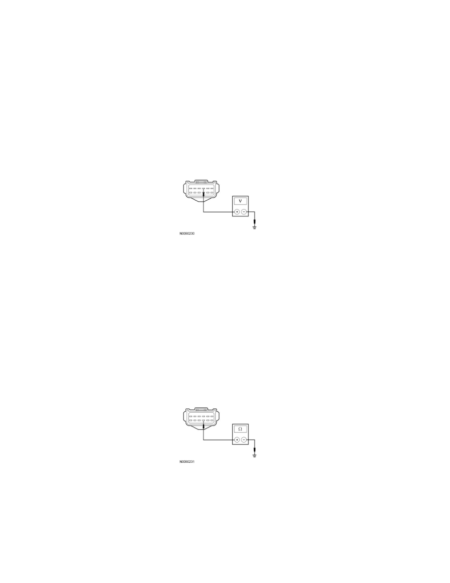
F1 CHECK THE HCM VOLTAGE SUPPLY CIRCUIT FOR AN OPEN
NOTE: HCM testing is carried out at the LH headlamp assembly connector.
-
Ignition OFF.
-
Disconnect: LH Headlamp Assembly C1021b.
-
Ignition ON.
-
Measure the voltage between the LH headlamp assembly C1021b-3, circuit CBB51 (BN), harness side and ground.
-
Is the voltage greater than 10 volts?
Yes
GO to F2.
No
VERIFY the Battery Junction Box (BJB) fuse 51 (5A) is OK. If OK, REPAIR the circuit. If not OK, REFER to the Wiring Diagrams to identify the
possible causes of the circuit short. CLEAR the
DTCs. REPEAT the network test with the scan tool.
-------------------------------------------------
F2 CHECK THE HCM GROUND CIRCUIT FOR AN OPEN
-
Ignition OFF.
-
Disconnect: Negative Battery Cable.
-
Measure the resistance between the LH headlamp assembly C1021b-9, circuit GD120 (BK/GN), harness side and ground.
-
Is the resistance less than 5 ohms?
Yes
GO to F3.
No
REPAIR the circuit. CONNECT the negative battery cable. CLEAR the DTCs. REPEAT the network test with the scan tool.
-------------------------------------------------