
Edge AWD V6-3.5L (2009)
-
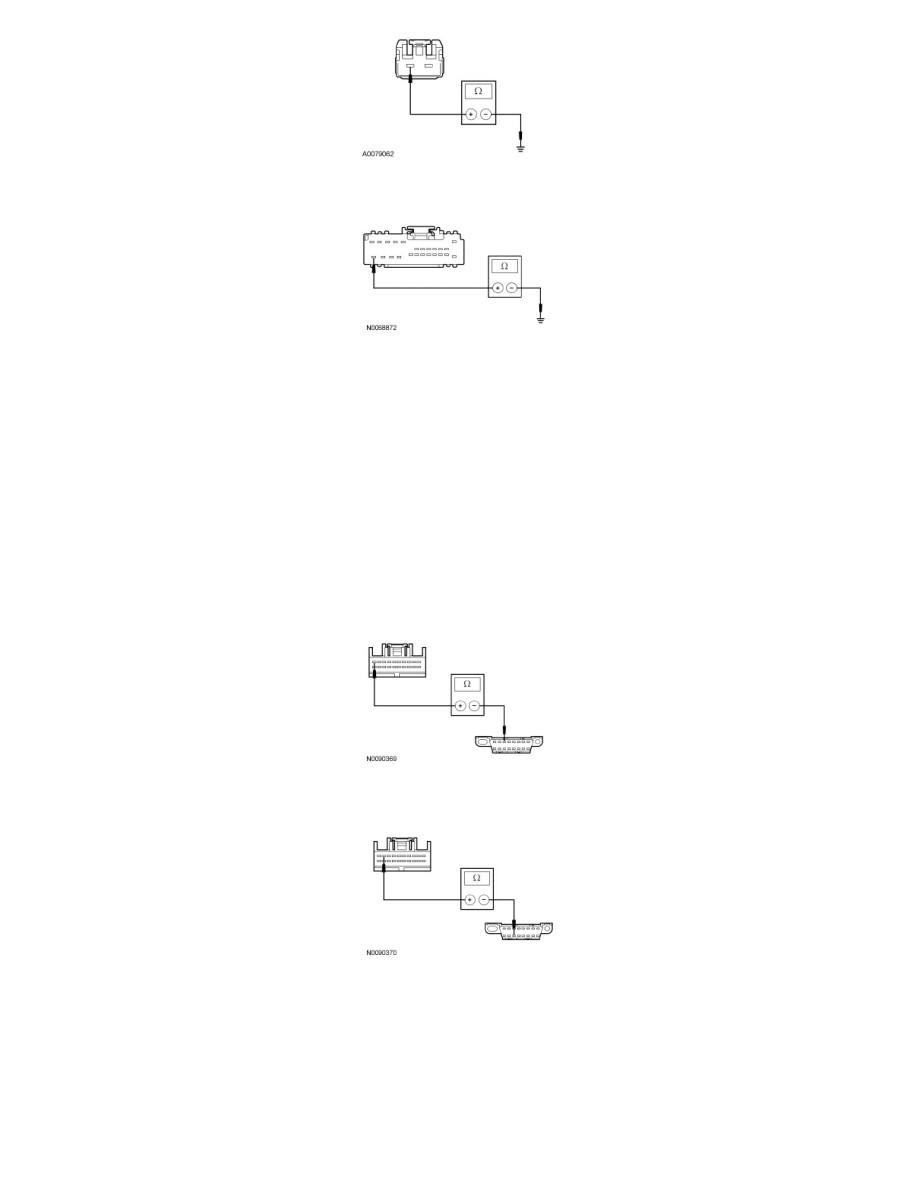
Measure the resistance between the DSM C3299b-24, circuit GD133 (BK), harness side and ground.
-
Are the resistances less than 5 ohms?
Yes
GO to O3.
No
REPAIR the circuit in question. CONNECT the negative battery cable. CLEAR the DTCs. REPEAT the network test with the scan tool.
-------------------------------------------------
O3 CHECK THE MS-CAN CIRCUITS BETWEEN THE DSM AND THE DLC FOR AN OPEN
-
Disconnect: DSM C3299d.
-
Measure the resistance between the DSM C3299d-10, circuit VDB06 (GY/OG), harness side and the DLC C251-3, circuit VDB06 (GY/OG),
harness side.
-
Measure the resistance between the DSM C3299d-9, circuit VDB07 (VT/OG), harness side and the DLC C251-11, circuit VDB07 (VT/OG),
harness side.
-
Are the resistances less than 5 ohms?
Yes
CONNECT the negative battery cable. GO to O4.
No
REPAIR the circuit in question. CONNECT the negative battery cable. CLEAR the DTCs. REPEAT the network test with the scan tool.