
Edge AWD V6-3.5L (2009)
14. Install the screw and the LH duct assembly.
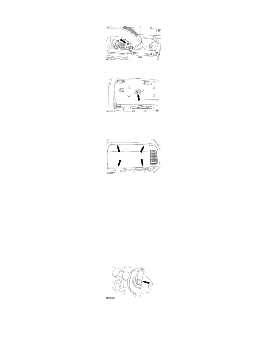
15. Install the screw for the LH duct assembly bracket in the front of the instrument panel.
16. NOTE: Make sure the 5 RH instrument panel finish panel retaining clips are fully seated in the instrument panel.
Install the RH instrument panel finish panel.
Edge
17. NOTICE: Do not install the passenger air bag module electrical connectors by the locking buttons. Damage to the locking buttons may
occur.
NOTICE: The passenger air bag module electrical connector locking buttons must be in the released position when the connector is being
installed or connector damage may occur.
NOTICE: The passenger air bag module electrical connectors are unique and cannot be reversed when connected to the passenger air
bag module. Match the electrical connector key to the keyway in the passenger air bag module. Do not force the electrical connectors into
the passenger air bag module. Damage to the connector or component may occur.
NOTE: RH side shown, LH similar.
With the locking buttons released, install the 2 passenger air bag module electrical connectors fully into the passenger air bag module and seat the
locking buttons.
18. NOTICE: Do not handle the passenger air bag module by grabbing the edges of the air bag trim cover. Damage to the air bag module
may occur.
NOTE: During passenger air bag module installation, make sure all the air bag trim cover clips are fully seated in the instrument panel.
Install the passenger air bag module trim cover rear-most clips into the instrument panel first. Then install the side trim cover clips working around