
Edge AWD V6-3.5L (2009)
to the forward-most clips seating each of them fully into the instrument panel.
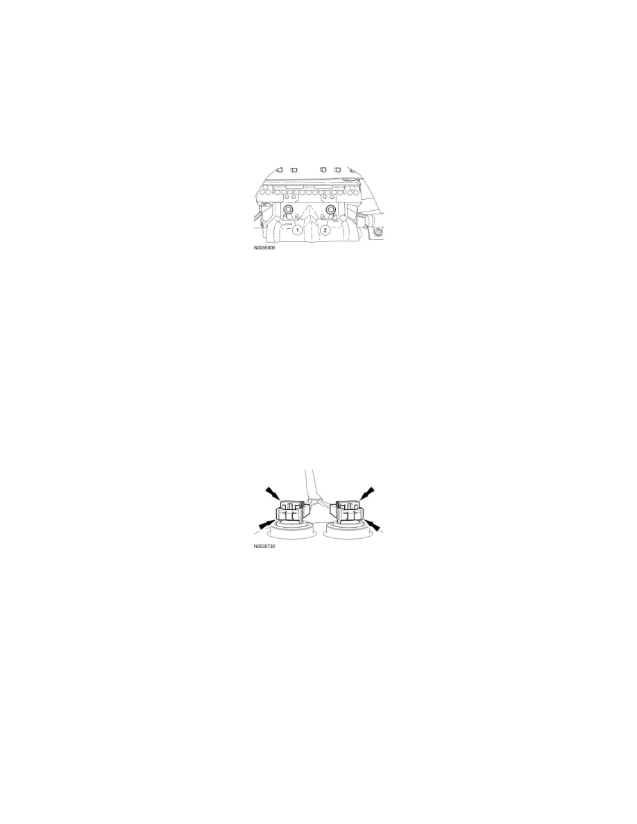
19. NOTE: To avoid a squeak or rattle condition, install the 2 passenger air bag module bolts in this order.
Install the 2 passenger air bag module bolts.
1. Install the inboard passenger air bag module bolt.
-
Tighten to 8 Nm (71 lb-in).
2. Install the outboard passenger air bag module bolt.
-
Tighten to 8 Nm (71 lb-in).
All vehicles
20. Hook the glove compartment door to the instrument panel. Close the glove compartment door.
-
If equipped, attach the glove compartment door dampener.
21. NOTICE: Do not install the driver air bag module electrical connectors by the locking buttons. Damage to the locking buttons may occur.
NOTICE: The driver air bag module electrical connector locking buttons must be in the released position when the connector is being
installed or connector damage may occur.
NOTICE: The driver air bag module electrical connectors are unique and cannot be reversed when connected to the driver air bag
module. Match the electrical connector key to the keyway in the passenger air bag module. Do not force the electrical connectors into the
passenger air bag module. Damage to the connector or component may occur.
With the locking buttons released, install the driver air bag module electrical connectors fully into the driver air bag module and seat the locking
buttons.
22. NOTE: Audible clicks will be heard when both wire clips are seated in the driver air bag module.
Align the driver air bag module locking pins to the steering wheel and, while pushing inward, seat the 2 driver air bag module locking pins to the
steering wheel wire clips.
-
When the 2 locking pins are seated in place, there should be an even gap between the driver air bag module trim cover and the steering wheel.
23. Turn the ignition from OFF to ON.
24. Install RCM fuse 46 (7.5A) to the SJB and install the lower kick panel fuse cover.
25. WARNING: Make sure no one is in the vehicle and there is nothing blocking or placed in front of any air bag module when the battery is
connected. Failure to follow these instructions may result in serious personal injury in the event of an accidental deployment.
Connect the battery ground cable.
26. Prove out the SRS as follows:
Turn the ignition from ON to OFF. Wait 10 seconds, then turn the ignition back to ON and monitor the air bag warning indicator with the air bag
modules installed. The air bag warning indicator will light continuously for approximately 6 seconds and then turn off. If an air bag SRS fault is