
Escape 2WD L4-122 2.0L DOHC VIN B Zetec SFI (2003)
Information Bus: Testing and Inspection
Communications Network
Initial Inspection
INSPECTION AND VERIFICATION
1. Verify the customer concern.
2. Visually inspect for obvious signs of electrical damage.
VISUAL INSPECTION CHART
Electrical
-
Central junction box (CJB) Fuse ROOM (10A)
-
Wiring harness
-
Connectors
-
Instrument cluster (IC)
-
Anti-lock brake system (ABS) control module
-
Restraint control module (RCM)
-
Generic electronic module (GEM)
-
Powertrain control module (PCM)
3. If the concern remains after the inspection, connect the diagnostic tool to the data link connector (DLC) located beneath the instrument panel and
select the vehicle to be tested from the diagnostic tool menu. If the diagnostic tool does not communicate with the vehicle:
-
check that the program card is correctly installed.
-
check the connections to the vehicle.
-
check the ignition switch position is in RUN.
If the diagnostic tool still dues not communicate with the vehicle, go to Pinpoint Test H. See: Pinpoint Tests/Pinpoint Tests/Test H
4. Go to Pinpoint Test PC. See: Pinpoint Tests/Pinpoint Test PC (Precheck)
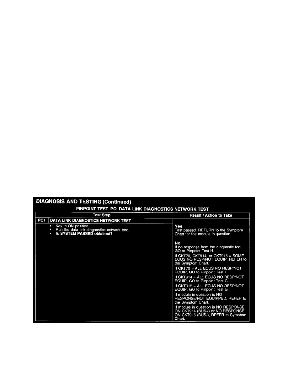
Pinpoint Test PC (Precheck)
PINPOINT TEST PC: DATA LINK DIAGNOSTICS NETWORK TEST
Test PC1
Test A
PINPOINT TEST A: THE ANTI-LOCK BRAKE SYSTEM (ABS) CONTROL MODULE DOES NOT RESPOND TO THE DIAGNOSTIC
TOOL