Escape 2WD L4-2.5L Hybrid (2010)

-
If a module fails to communication during the network test, GO to Symptom Chart. See: Symptom Related Diagnostic Procedures
6. Retrieve and review the DTCs.
-
If the DTCs retrieved are related to the concern, go to DTC Charts. Follow the non-network DTC diagnostics (B-codes, C-codes, P-codes)
prior to the network DTC diagnostics (U-codes). For all other DTCs, refer to the Diagnostic Trouble Code (DTC) Chart in Body Control
Systems. See: Diagnostic Trouble Code Descriptions See: Body and Frame/Body Control Systems/Testing and Inspection/Diagnostic Trouble
Code Descriptions/Diagnostic Trouble Code (DTC) Chart
-
If no DTCs related to the concern are retrieved, GO to Symptom Chart. See: Symptom Related Diagnostic Procedures
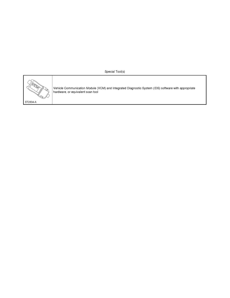
Special Tools Used With Diagnostics
Module Configuration
Inspection and Verification
Module Configuration
Inspection and Verification
This provides step-by-step module configuration procedures. Carry out the Programmable Module Installation (PMI) procedures when another
diagnostic/repair information directs to carry out configuration or when DTCs from the below list are present: See: Programming and Relearning
Principles of Operation
Module Configuration
Principles of Operation
Configurable modules accommodate a variety of vehicle options, eliminating the need for many unique modules for one vehicle line. These modules
must be configured when replaced as part of a repair procedure. Configurable modules should not be exchanged between vehicles since the settings are
unique to each vehicle. Failure to configure a new module may result in incorrect operation and/or DTCs setting.
The following are the 3 different methods of configuration:
-
Programmable Module Installation (PMI)
-
Module reprogramming ("flashing")
-
Programmable parameters
Some modules do not support all 3 methods.
Definition of Terms
The following are definitions of configuration terms:
Programmable Module Installation (PMI)
PMI is a scan tool process which configures settings in a new module. Data used for the PMI process is automatically downloaded from the original
module and stored when a scan tool session is started. If this data cannot be retrieved from the module being replaced, the scan tool may prompt for
As-Built data entry or display a list of parameter values that need to be manually selected. Some modules are reprogrammed during PMI when a
strategy/calibration update is available. To carry out PMI, refer to Programmable Module Installation (PMI) See: Service and Repair.
NOTE: It is important that the scan tool identifies the vehicle and obtains configuration data prior to removing any modules. The new module must be
able to communicate with the scan tool in order to carry out PMI. See: Programming and Relearning
Module Reprogramming
