
Escape 2WD L4-2.5L Hybrid (2010)
previously determined.
-
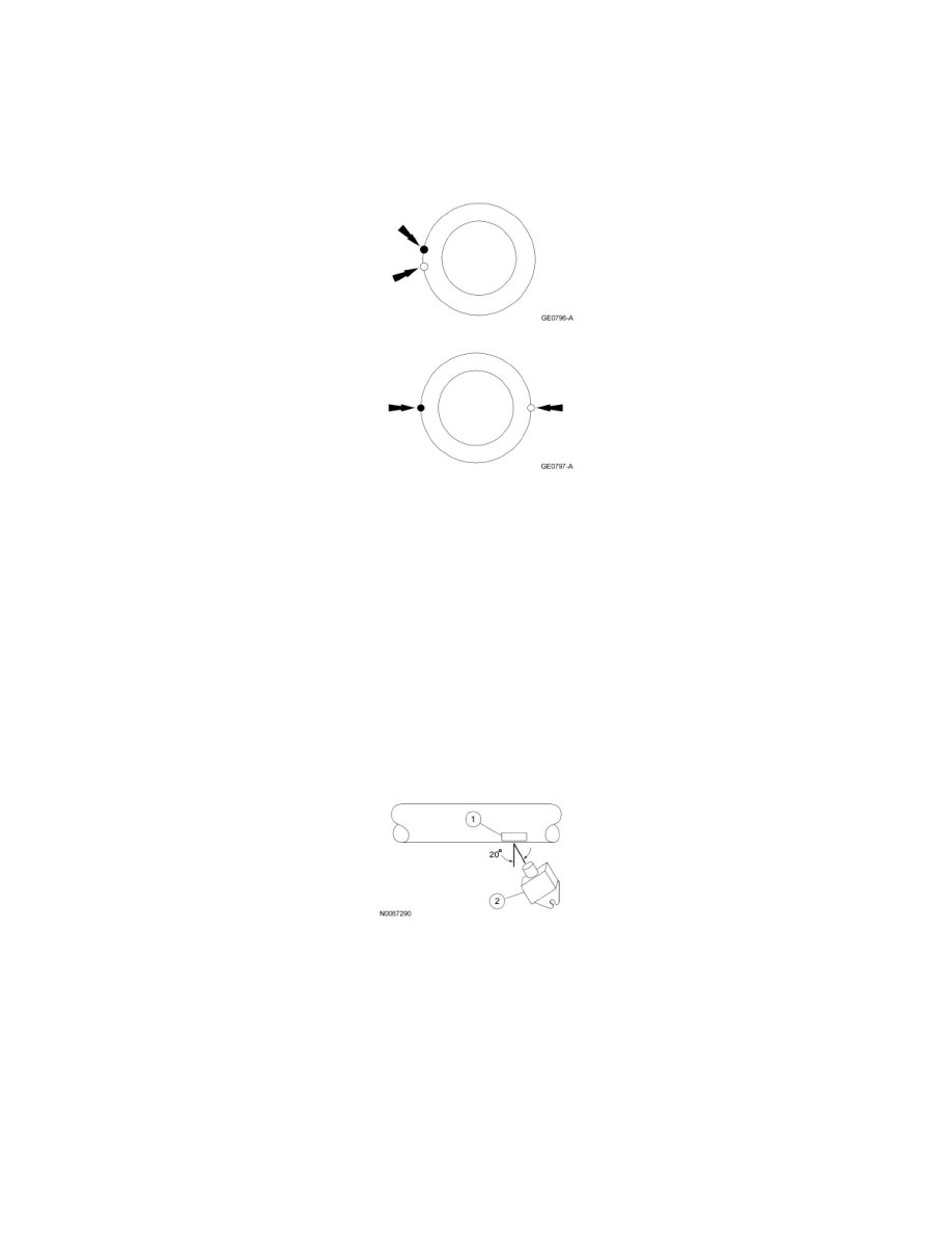
If the index marks are close together, within 25 mm (1 in), the driveshaft is eccentric. Install a new driveshaft.
-
If the marks are on opposite sides of the driveshaft, 180 degrees apart, the slip yoke or pinion flange is responsible. Check the pinion flange
runout. If the pinion flange runout exceeds specifications, a bent pinion is indicated.
-
If the pinion flange and pinion runouts are within specifications, road test and check for the vibration at the road test speed. If the vibration
persists, balance the driveshaft. For additional information, refer to Driveshaft Balancing in this procedure.
Driveshaft Balancing - Using the Mastertech(R) Series MTS 4000 Driveline Balance and NVH Analyzer (Vetronix)
All vehicles
1. Install the Mastertech(R) Series MTS 4000 Driveline Balance and NVH Analyzer (Vetronix) to the vehicle.
2. Working under the vehicle, install an accelerometer. The accelerometer can be attached and mounted near either the transmission or differential
end of the driveshaft.
3. Clean an area of the driveshaft and install the reflective tape, then install the photo-tachometer sensor. The sensor should be placed at
approximately a 20-degree angle from perpendicular to the surface of the reflective tape. Make sure the sensor does not get moved during the
balance procedure.
1. Reflective tape.
2. Photo-tachometer sensor.
4. Using the Mastertech(R) Series MTS 4000 Driveline Balance and NVH Analyzer (Vetronix), run a driveshaft balance test with the driveshaft
unmodified.
Vehicles with tapped pinion flanges
5. Label the tapped holes in the pinion flange numerically, starting at the top hole as 1. Mark the remaining holes 2, 3 and 4. Label in the direction of
rotation.